bleenc starter kit
bleenc starter kit is designed to support and simplify the first approach to bleenc system and its underlying BLE-based localization platform.
The starter kit is provided with a practical guide to become familiar with the core concepts, components and operating principles of the bleenc platform.
The kit is delivered preconfigured and ready to be used, with no complex setup required and it allows to test and validate the core and distinctive features of bleenc system in real operating conditions, using a set of typical reference use cases, which can also be tested in parallel, depending on the deployment scenario.
At the same time, the starter kit includes the full set of bleenc system functionalities and multiple device types, allowing users to gain familiarity through typical use cases and to progressively explore all the platform’s capabilities.
The typical bleenc use cases are:
- Localized emergency calls
- Asset tracking
- Find-by-light identification
- E-paper tags management
- BLE sensors monitoring
Components
bleenc starter kit is composed by the following software and hardware components.
bleenc software
bleenc software is provided installed in cloud and can be remotely reached via web interface.
Note: alternatively, bleenc can be provided pre-installed on a Mini PC on request.
The software is necessary for devices management, configuration and localization. bleenc is provided with secure APIs for software integration into third party applications.

bleenc gateways
bleenc gateways (mod. TinyGateway PoE) allow a real time monitoring of bleenc devices, working as BLE scanners. Using the gateways it is possible to receive in real time, with a latency in the order of fractions of a second, tag information, including motion or still state, button pressure, alarm state (following a shock or fall event, if configured).
In addition, gateways support bi-directional communication with bleenc tags, allowing to send commands to a tag to blink a LED, update e-paper tag content or else update tags’ configuration.
Gateways are used to provide a first-level localization infrastructure, by providing real-time approximate tag position at zone level.

bleenc beacons
bleenc beacons (mod. Ultra Zero) work as standard BLE beacons. Beacons are used to create localization micro-zones based on proximity estimate, building the second-level localization infrastructure and providing tag’s position refinement. Beacons can be used to identify a room, by installing one beacon per room on the ceiling, or more beacons for bigger-sized rooms, or to identify a workstation, by installing a beacon for each workstation.
Unlike gateway-based positioning, beacon-based positioning is updated only when specific conditions are met. Possible alternatives are:
- periodic update: beacon scan information is periodic (minimum interval 1 min);
- event-based update, such as button pressure, state switch from moving to still, shock detection;
- update on request: send a command to the tag to request beacon-based position update.

bleenc tags
The starter kit is provided with preconfigured bleenc tags of different types:
- 2 wearable bleenc tags with button (mod. SafeX Lite STD)
- 2 asset bleenc tags (mod. Slim Tag)
- 2 asset bleenc tags with LED (mod. Forte+ LED)
- 2 e-paper tags with button (mod. ETag29B1)
BLE Sensors
The starter kit includes also preconfigured BLE sensors:
- 1 BLE temperature and humidity sensor (mod. TagX SHT)
- 1 BLE acceleration sensor (mod. TagX STD)
Devices summary
Note: the starter kit can be provided with different device models and quantities with respect to the standard configuration, upon client’s request.
| Device type | Device model | Quantity | Image |
|---|---|---|---|
| bleenc gateways | TinyGateway PoE | 4 | 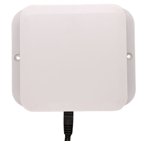 |
| bleenc beacons | Ultra Zero | 6 | 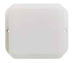 |
| bleenc tags | SafeX Lite | 2 | 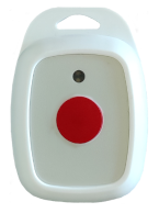 |
| Slim Tag | 2 | 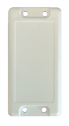 |
|
| Forte+ LED | 2 | 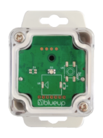 |
|
| ETag29B1 | 2 | 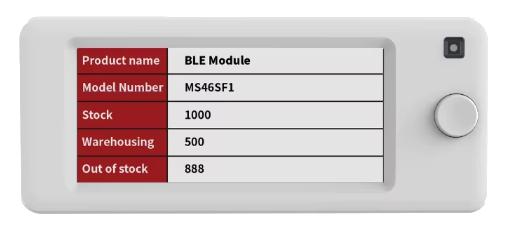 |
|
| BLE sensors | TagX SHT | 1 | 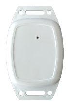 |
| TagX STD | 1 | 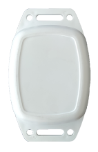 |
Devices installation
bleenc starter kit allows to build a basic localization infrastructure of bleenc system, based on 4 gateways and 6 beacons.
The starter kit is designed to test the bleenc system in environments composed by rooms and transit areas (e.g., corridors, halls,...), like the ones that can be found in hospitals, nursing homes, offices, laboratories. This type of environment is the ideal representation of the application of bleenc localization system. However, bleenc can also be used in other types of environment.
Gateways are used to provide a first-level localization infrastructure, by providing real-time approximate tag position at zone level. bleenc gateways provide radio coverage in the test area.
Gateways should be installed on the ceiling (in case of ceilings with a height of max 3 mt) or, alternatively, on walls at a height of approximately 2.5/3 mt.
Note: a new version TinyGateway, specifically designed for ceiling installations, is under release.
Beacons are used to provide the second-level localization infrastructure, to provide tag’s position refinement. Beacons can be used to create micro-zones for localization, such as rooms (one or more beacons per room depending on size), workstations, machineries,...
Below are proposed two typical installations with their corresponding graphic representations.
Scenario A: corridor with rooms
Install the gateways along the corridor of the test area. The gateways can be installed on the ceiling or on walls, approximately at 2.5/3 mt height.
Install the beacons on the ceiling in the centre of the rooms. If necessary, multiple beacons per room may be installed.

Scenario B: open area with workstations
Install the gateways at the corners of the test area. The gateways can be installed on the ceiling or on walls, approximately at 2.5/3 mt height.
Install the beacons over or in front of each workstation.

Network architecture and requirements
Cloud installation
In cloud-based installations, the bleenc server is hosted in cloud.
All the gateways are connected to the same local LAN via PoE (Power-over-Ethernet).
The network infrastructure must allow inbound/outbound connectivity between the gateways and the server, and the gateways must be able to reach the bleenc service on the configured network port.

MiniPC installation
bleenc can be provided pre-installed on a Mini PC on request.
In this type of installation, both the gateways and the MiniPC must be installed on the same local network. The gateways connect to the LAN via PoE (Power-over-Ethernet).
In this setup, the gateways must be able to reach the bleenc service on the configured network port.

First start
Below are described the steps to follow to install the system and start testing it.
- bleenc software is provided preconfigured, installed in cloud and reachable remotely at the web address communicated to the client directly.
- The gateways are provided preconfigured with DHCP enabled and to connect automatically to bleenc instance at power on.
Install the gateways, following the instructions described in Devices installation, power them on and connect to the LAN (PoE or Ethernet + USB-C) and check that the gateways are connected and visible in bleenc interface, in Gateways section.
- Install bleenc beacons as described in Devices installation.
Check that beacons are listed in the bleenc interface, Tags section -> Beacons view.
Note: from a system perspective, bleenc beacons are managed as bleenc tags. The main difference is that beacons are fixed, while tags are typically mobile.
- Check that tags and sensors are visible in the bleenc interface: bleenc tags in the Tags section, BLE sensors in the Sensors section.
Note: The devices in the starter kit are supplied activated, while those in standard production orders will be supplied to be activated.

- Upload and configure the map of the test environment following the steps described in Map upload and setup.
- Place the gateways on the map, in positions corresponding to their actual locations.
- Place the beacons on the map, in positions corresponding to their actual locations.
- The system is now ready and can be tested with the different use cases, as described in How to test the use cases.
Map upload and setup
In Maps section it is possible to upload a map to have a reference position of the fixed devices (gateways and beacons) and mobile ones (tags). Steps for map upload and setup are the following:
- Go to the Project’s section, and then to the Maps section and press on Add new map.
- Upload the map image.
- Set the map scale. Select the Set scale tool
 and select two reference points, between which you know the distance. The scale is necessary for the correct position and distance estimation.
Note: horizontal and vertical guides can be added for greater precision.
Once you have entered the distance between the two points, the software will compute the scale of the map. - Add a map description and save.

- Create beacon zones.
Note: for the second-level localization (using the beacons), the beacons must be associated to a zone. If a beacon is not in a map zone, it will not be used for tag localization.
To create a zone, press on the add new zone tool , fill in the ID and zone description and draw the zone: using the left mouse button, press in a spot where one vertex of the zone will be and drag from that point to build a rectangle. If the zone is an irregular polygon, other vertices can be added, by pressing Shift and clicking with the mouse on one of the vertices. Move the vertices to achieve the desired shape and press enter.
Note: press esc to exit the zone creation tool. Horizontal and vertical guides can be added for greater precision. Press Ctrl to stick a vertex to the guide.
- Place devices on the map. It is possible to place gateways and beacons on the map and, if necessary, also the tags to assign them a fixed position. Press on add new device tool
 , select a device and place it on the map.
Note: horizontal and vertical guides can be added for greater precision. Press Ctrl to stick a device to the guide.
APIs and Events
The software provides a set of APIs and Events designed to expose relevant system information, including device status, configuration, position data, and more. Events are generated whenever a change occurs in the system, such as state transitions, position updates, button presses, and others.
Both APIs and Events can be used to integrate the software into final applications, enabling real-time monitoring and interaction with the system.
How to use APIs
The complete list of available APIs is available in the software web interface, in the API section.
To comply with cybersecurity regulations, on the first start, the API access is disabled.

The user can choose between two possible access rules:
- Basic - the user has to specify a Username and Password to use when calling the API;

- Bearer JWT - the most secure authorization mode, described here. To use this authentication rule, the user has to generate a JWT Token in JWT Tokens section.

API JWT Tokens
To authenticate using Bearer JWT method, a JWT Token has to be generated to be used when calling an API. To create a new Token press on  and fill in the following fields:
- Description of the JWT token;
- Expires to decide if the token expires or not. In case this field is checked, the user has to set an expiry date and time;
- IP addresses is the list of IP addresses that can call the APIs. If left blank, all IP addresses will be allowed;
- Access Rule options are:
- Allow all to allow the access to all API calls;
- Allow selected APIs to allow to call only the selected API calls;
- Deny selected APIs to deny to call selected APIs;
- Allow all to allow the access to all API calls;
- Max invocation per hour is the maximum number of API calls that can be invoked per hour with this JWT token.
Call the APIs with JWT Token
To call the APIs, the following steps are required:
- Download the generated token;
- when calling any API, select Bearer Token as the authorization method and use the token downloaded in the previous step.
If a valid token is not provided, the API call will return an authorization error.

How to receive events
The system generates events when there are updates, such as button pressure, state change, etc. Events are:
- natively broadcasted through the MQTT interface, on the topic blueup/bleenc/events/
; 
- received as push notification using SSE technology (Server sent events) by calling the API
/api/event-stream;
- in bleenc web interface, in the Events Logs section.

How to test the use cases
For each use case, this guide describes the typical use case applications, how the relevant information is displayed in the bleenc web interface, and how to access the same information through API calls or event notifications.
Localized emergency call
The localized emergency call use case allows to simulate typical applications, such as:
- Healthcare: nurse call;
- Workplace safety: alarm call;
- Industry: notification of start/end of processing, assistance request.
The localized emergency call can be tested with SafeX Lite STD wearable tags.
The devices are configured to:
- continuously transmit a state packet, containing information used by the system for estimating first-level position and for updating tag status;

- transmit real-time notification of button-press event (with ACK) with type information (single/double/triple click, long press…);

- transmit the information about the nearby beacons, used for second-level position estimate (zone detection).

Web interface
The first-level position, the motion state, the button pressure and the second-level position, together with other tag’s information are displayed in the bleenc web interface, in the Tags table.

Events
The above information can be retrieved as events, as described in How to receive events.
The reference events are:
- tagLocationUpdated – in “location” object are contained tag’s estimated first and, when available, second-level position;
- tagButtonPressed – event containing the tag button pressure information.
API
The latest estimated tag position can be retrieved via HTTP request /api/tags or /api/tag/{tag_ID}, in the “location” object.
Asset tracking
The asset tracking use case allows to simulate typical applications, such as:
- Healthcare: medical devices tracking;
- Industry: containers / carts / jig tracking;
- Offices: electronic devices tracking.
The asset tracking can be tested with Slim Tag asset tags.
The devices are configured to:
- continuously transmit a state packet, containing information used by the system for estimating first-level position and for updating tag status;

- when the tag stops moving, transmit the information about the nearby beacons, used for second-level position estimate (zone detection).

Web interface
The first-level position, the motion state and the second-level position, together with other tag’s information are displayed in the bleenc web interface, in the Tags table.

Events
The above information can be retrieved as events, as described in How to receive events.
The reference event is tagLocationUpdated – in “location” object are contained tag’s estimated first and, when available, second-level position.
API
The latest estimated tag position can be retrieved via HTTP request /api/tags or /api/tag/{tag_ID}, in the “location” object.
Find-by-light identification
The Find-by-light asset identification use case allows to simulate typical applications, such as:
- Healthcare: medical equipment / bed / wheelchair identification
- Industry: containers / carts / jig identification
- Intra-logistics: asset identification.
This use case can be tested together with Asset Tracking use case.
The find-by-light asset identification can be tested with Forte+ LED asset bleenc tags with LED.
In addition to the previous use-case (Asset Tracking), the devices are configured to:
- receive real-time commands to trigger the LED.
Note: the Forte+ LED asset tag is equipped with a single RGB LED (LED 0). No buzzer or vibration motor is present.
Web interface
The commands can be sent to the devices in the bleenc Web interface, the Tags table, by pressing on the command button and composing the command to send to the tag.

Events
The positioning information can be retrieved as events, as described in How to receive events.
The reference event is tagLocationUpdated – in “location” object are contained tag’s estimated first and, when available, second-level position.
API
The latest estimated tag position can be retrieved via HTTP request /api/tags or /api/tag/{tag_ID}, in the “location” object.
The tag can be commanded via HTTP /api/command request. The request body has to contain the command to send to the tag, similarly as in the web interface commanding. Refer to the API documentation included in the bleenc web interface for more information.

E-paper tags management
The e-paper tags management allows to simulate typical applications, such as:
- Healthcare: identification of patients and hospital equipment;
- Manufacturing: identification of orders and raw materials;
- Offices: occupancy / booking of meeting rooms, offices, work stations.
The use cases can be tested with bleenc e-paper tags ETag29B1.
The devices are configured to:
- receive real-time commands to update information displayed on the e-paper display.
Display content update
The E-paper tag display is preconfigured with the layout shown in figure below.
The layout is composed by 8 frames:
- frames 0 – 5 configured as text;
- frame 6 configured as Barcode;
- frame 7 configured as icon.
In the following is described how to update the display layout content, with the current layout.

Web interface
The e-paper display content may be updated via bleenc web interface, in the Devices → Tags panel, by pressing on Send command → Write e-paper.
A form to fill in will appear, based on how the e-paper tag is configured.

API
The e-paper display content may be updated via HTTP /api/epaper/write request (refer to the API documentation included in the bleenc web interface). The “frames” object structure must be built based on the e-paper configuration.

Display layout configuration
The e-paper tag display resolution is 296 (width) x 129 (height) pixels, with the origin (0,0) point located at the top-left corner of the screen.
The display layout can be modified in Tag settings, in the “E-paper” class configuration.

The display can be divided into up to 16 frames, each one can be configured as:
- rectangle
- text
- QR code
- Barcode
- Icon
For each frame, both background and foreground colors can be selected among white, black and red. Alignment and text size are also configurable.
The frames can be arranged freely on the display, taking special care in defining the origin (x, y), width and height of each frame.
Make sure that the frames are non overlapping, for tag’s correct configuration and update.
After changing the display layout configuration and saving it, update the display content based on the new layout, following the description above.
BLE sensors monitoring
The monitoring of BLE sensors allows to simulate typical applications, such as:
- Healthcare: environmental parameters, room occupancy, door/window opening;
- Industry: vibration, environmental parameters;
- Offices: environmental parameters, rooms occupancy, desk occupancy.
The starter kit includes two BLE sensors:
- TagX SHT: temperature and humidity sensor;
- TagX STD: acceleration sensor.
bleenc allows to integrate and monitor BLE sensors from any third-party vendor.
The devices are configured to:
- continuously transmit a sensor advertising packet, containing sensors information.
Web interface
Sensors information are shown in tabular form in the Sensors section.
Events
The above information can be retrieved as events, as described in How to receive events. The reference events, containing sensors data update, are:
- sensorAccelerometerChanged
- sensorHumidityChanged
- sensorTemperatureChanged
API
The latest sensors’ measured parameters can be retrieved via HTTP /api/sensors call. This request returns the list of sensors detected by the system and the latest measured environmental parameters.