Smart Industry Starter Kit
Smart Industry Starter Kit is the optimal solution if you want to test MeshCube platform for industrial environments (manufacturing, logistics, ...). This Starter Kit includes devices suitable for industrial installation and allows to test both asset tracking and personnel locating applications.
Hardware components
In the table below are listed the hardware components that are included in the starter kit.
| Device | Quantity | Image |
|---|---|---|
| MeshCube installed in cloud or on a MiniPC with 1-year license |
1 | 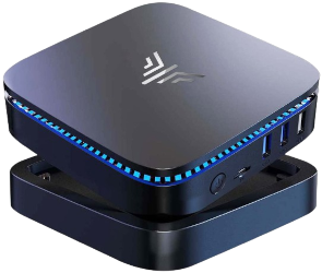 |
| TinyGateway PoE | 1 | 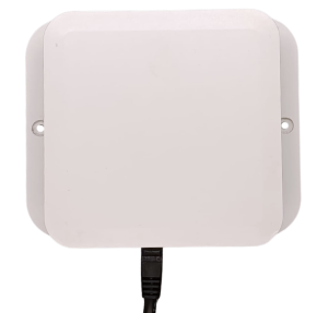 |
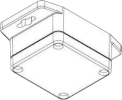
| Brick anchors | 10 | 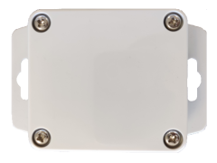 |
| TagX asset tags | 6 | 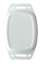 |
| SafeX Lite wearable tags | 2 | 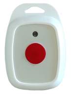 |
Prerequisites
Prerequisites for using the starter kit are:
- LAN (Local Area Network). Your LAN should be provided with DHCP server to be able to retrieve the MeshCube Server (if installed on MiniPC) and TinyGateway PoE IP addresses.
- A PC/Laptop with LAN (or WLAN) interface and web browser.
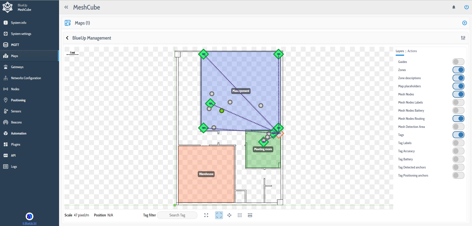
Setup
The following steps describe the complete setup of the MeshCube starter kit. Please follow each step as suggested.
Step 1: Server setup
If MeshCube software is installed in cloud, the system is ready to be used and can be accessed at the agreed url.
In case of MeshCube preinstalled on a MiniPC, follow the steps described below:
- Power-up MeshCube Server using provided Power Supply Unit (PSU) and connect it to your LAN.
- Connect PC/Laptop to your LAN.
- Find the local IP address of the MeshCube Server.
On your router interface MeshCube Server is listed with hostname meshcube-XXXXXX, where XXXXXX is a number.
Otherwise, if mDNS service is active in your network, you can reach the MeshCube interface atmeshcube.local
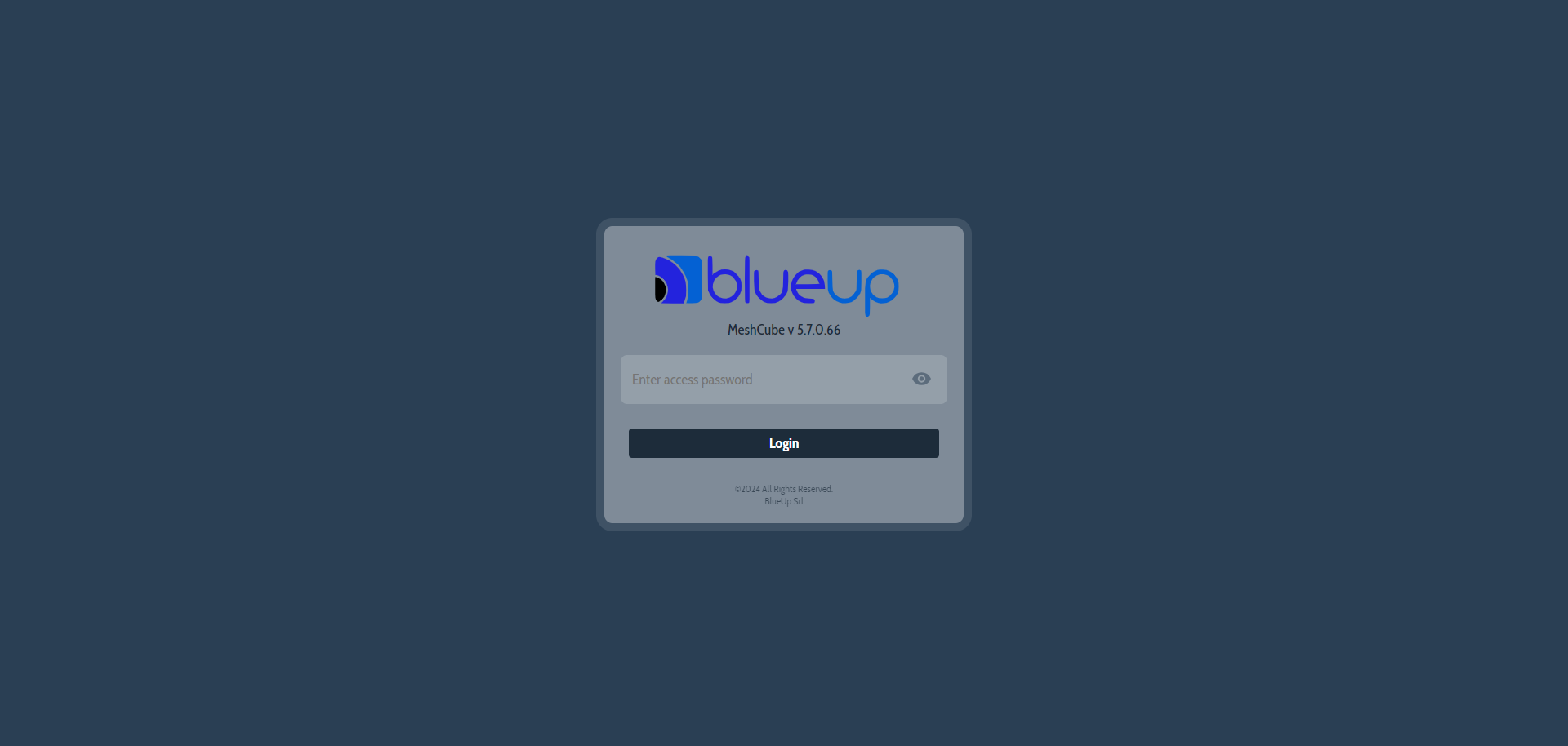
On your PC/Laptop, using the web browser, open:
- local IP of the MeshCube Server (local IP found in previous step) or by typing
meshcube.local, if the server is connected to the local network and istalled on premises; - the provided URL, if the software is installed in cloud.
Login the MeshCube web interface using the provided password.
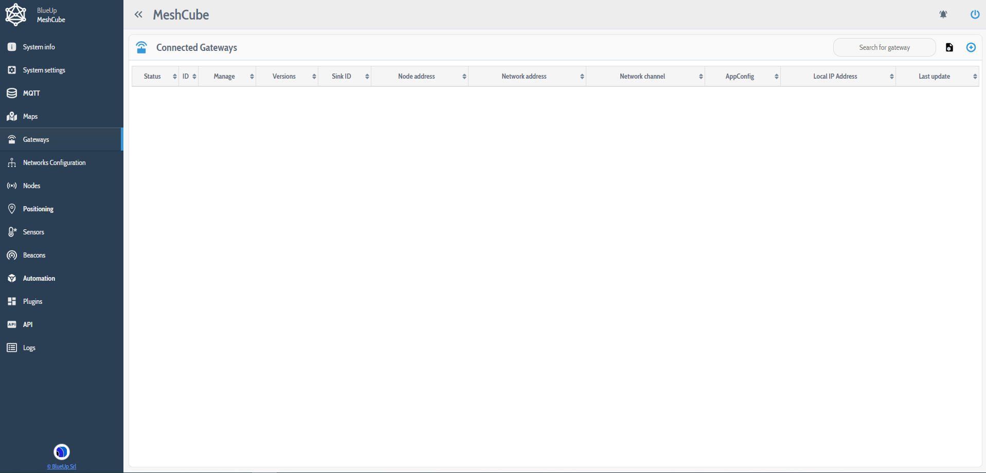
Step 2: Gateway setup
Refer to the TinyGateway PoE manual for gateway power on, installation and configuration.
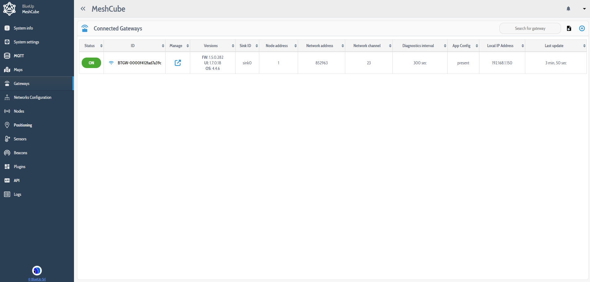
Go to the section Gateways. At the first start no gateway is connected to the system.
To connect the provided gateway to the system there are different possibilities, based on the software installation:
- For on premises installations, the MiniPC and the gateway should be installed in the same LAN.
Press to search and connect the gateway to the system. Press on
  button of the coresponding gateway to connect it to the system.
- In case of cloud installation, the steps to follow are:
- Retrieve the MQTT Broker credentials;
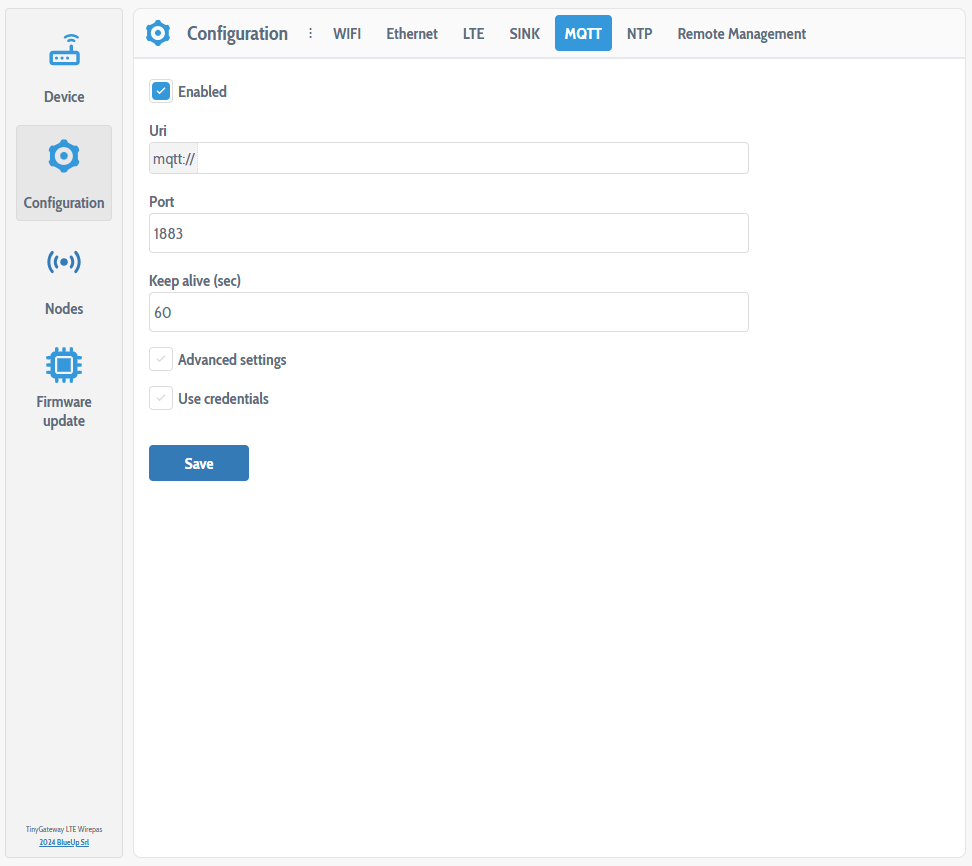
- Connect to the web interface of the gateway;
- In Configuration -> MQTT enter the MQTT Broker connection parameters;
- Save the configuration and reboot the gateway.
The Gateway is now listed in the Connected Gateways section and starts communicating with MeshCube software.
Step 3: Devices configuration
All the devices (tags and anchors) are shipped in a low power consumption mode, to reduce energy consumpion during transportation.
-
First, a working configuration for the devices has to be prepared.
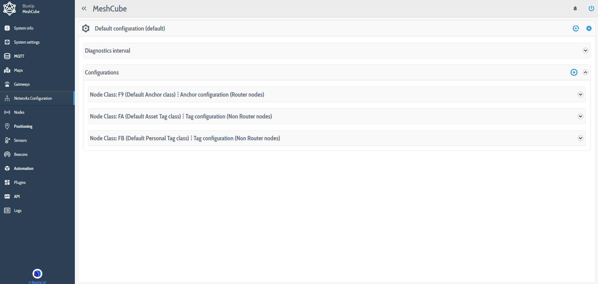
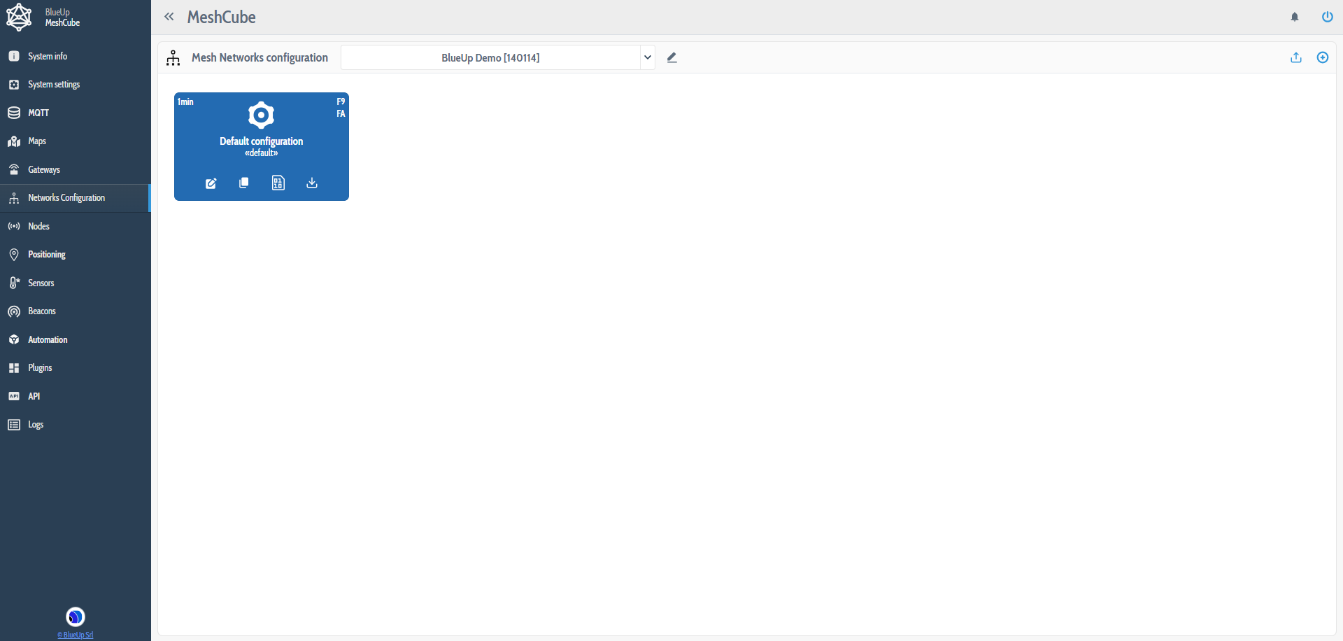
The configuration can be set from the MeshCube web interface, in Networks Configuration section. Network configuration includes both Anchors and Tags configuration parameters. The default device Classes are defined as follows:- F9 - default Anchor class
- FA - default Asset Tag class (tags suitable for positioning and tracking of assets)
- FB - default Personal Tag class (tags suitable for positioning and tracking of people)
- Other node classes can be defined. Refer to MeshCube User guide for more information.
-
Edit
 the Default Configuration to set a working configuration.
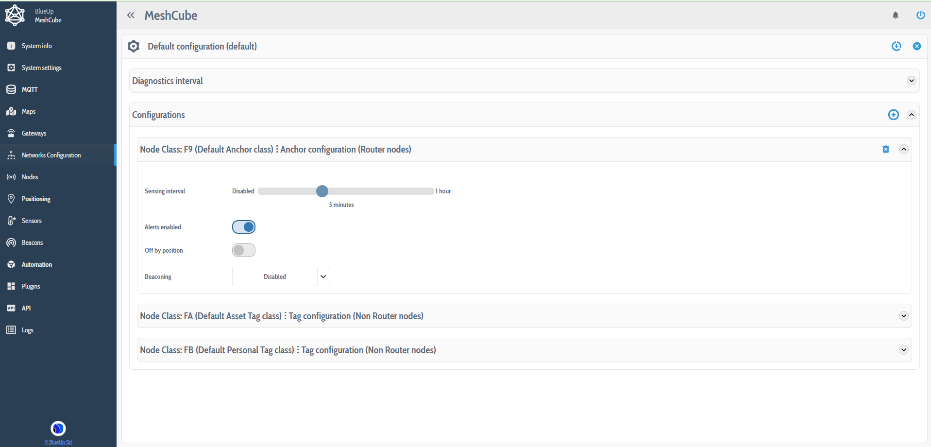
In the following is summarized a suggested default configuration, but the user can change it, based on the needs.
Router devices configuration Sensing interval 5 min Alerts enable On Off by position Off Beaconing Disabled
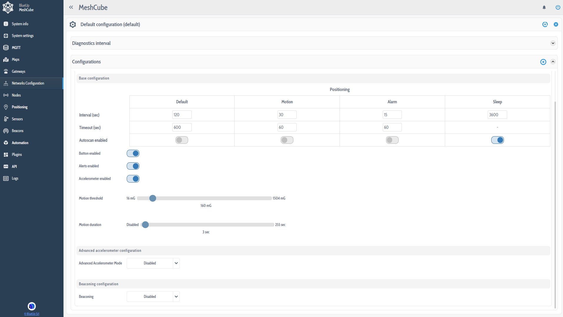
| Non router devices configuration | |
|---|---|
| Default positioning interval | 120 s |
| Default timeout | 600 s |
| Default autoscan | Off |
| Motion positioning interval | 65 s |
| Motion timeout | 90 s |
| Motion autoscan | Off |
| Alarm positioning interval | 15 s |
| Alarm timeout | 60 s |
| Alarm autoscan | Off |
| Sleep positioning interval | 3600 s |
| Sleep autoscan | On |
| Button enabled | On |
| Alerts enabled | On |
| Accelerometer enabled | On |
| Motion treshold | 160 mG |
| Motion duration | 3 s |
| Advanced accelerometer | Disabled |
| Beaconing | Disabled |
3. Save  and apply
  the configuration to the nodes of the network.
Make sure that all the devices are switched on and take the correct configuration.
- Brick anchors are shipped in Off by position mode.
This means that they are switched Off when in horizontal position and they are switched On in any other position, as shown below.
| Anchor Off |  |
||
| Anchor On | 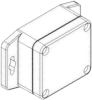 |
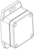 |
 |
Rotate all the anchors in a non-horizontal position to disable the off-by-position mode. After, the router devices will start to appear in the system and will take the configuration.
- When Mesh Tags are in Ultra-Low-Power Configuration (first time you receive them) you need to wake them up in order to forward the configuration command. The wakeup procedure varies based on the presence or not of a button on the device:
Mesh Tags without button shake the tag Mesh Tags with button press the button
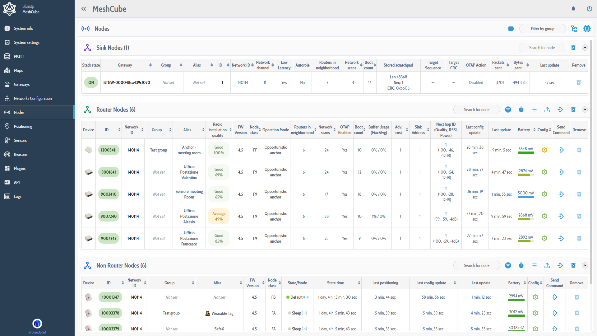
To check if the Anchors and Tags have updated their configuration with the new one, go to Devices section and check the Config column. The Config icon can have one of four colors:
- Grey: the system has not received the configuration for the device yet. This state is usually displayed at the startup of the system.
- Red: the configuration of the device is different from the Network Configuration set in the interface. It can happen, for example, when the new configuration has been set but the devices have not updated the configuration yet.
- Yellow: the node class configuration in not present in the latest Network Configuration. This can happen since it is possible to add or remove device classes when configuring the devices in the network.
- Green: the device is updated to the latest configuration.
Once all the devices (anchors and tags) are listed with Green or Yellow Config icon, the system is configured and you can start using it.
Devices setup and installation
-
Install the anchors in the desired position. For anchor installation tips refer to the following guide.
-
In the Maps menu, click on
to create a new map.
Upload the file containing the map. When uploading the map, you will be requested to specify the scale of the map (in pixels/mt). The accuracy of this value is required for maximum accuracy of the localization.
-
Create the Zones on the map. (The zones are not mandatory) In Actions menu press on Create new zone.
Using the left mouse button, press in a spot where one vertex of the zone will be and drag from that point to build a polygon. Release the mouse button. If the zone is not squared, but is an irregular polygon, other vertexes can be added. To add a new vertex, press Shift and click with the mouse on one of the vertexes. The new vertex will be added on the right with respect to the vertex on which you have pressed.
To move a vertex, press and drag it in the desired position (press Ctrl to stick the vertex to the guides).
When the zone is setup, press Enter to save the created zone.
-
Select Place Sink/Routers on the map in Actions menu, select the Sink or Router to place on the map and place it on the map. To move a Sink or Router:
- right click on it and a menu will appear, from which it is possible to move or delete a node;
- or press Shift and drag the router. Release and press YES if the position if right.
- Each Mesh Anchor should be placed in the same position where it is physically installed: take care of Mesh Anchor S/N to uniquely identify each device through its ID. The ID of each device is composed by the Model Number and Serial Number, that is printed on the sticker of each device, as follows:
Model Number = XX
Serial Number = YYYYYY
Once everything is setup, it will be possible to monitor the position of the Tags, evaluated based on the signal strength between tags and anchors.