bleenc system guide v.2.x
bleenc® is a proprietary localization platform developed by BlueUp based on the Bluetooth Low Energy (BLE) standard.
bleenc combines Bluetooth real-time location and tracking capabilities with bidirectional communication.
With its low-energy wireless protocol, data encryption security features, flexible localization methods, and scalable architecture open to third-party BLE devices, bleenc sets a new performance standard for RTLS systems.
bleenc is provided with a user-friendly web interface that can be used for configuration and monitoring of bleenc devices.
bleenc can be installed either on premises or in the cloud.
For assistance in selecting or configuring a suitable server, please contact BlueUp Support by opening a ticket or by writing an email to support@blueupbeacons.com.
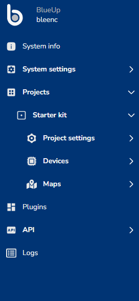
bleenc web interface, described here, is divided into sections for a user friendly navigation.
In the upper right corner of the web interface there is the notification center  where are shown the useful notifications from the system to the user.
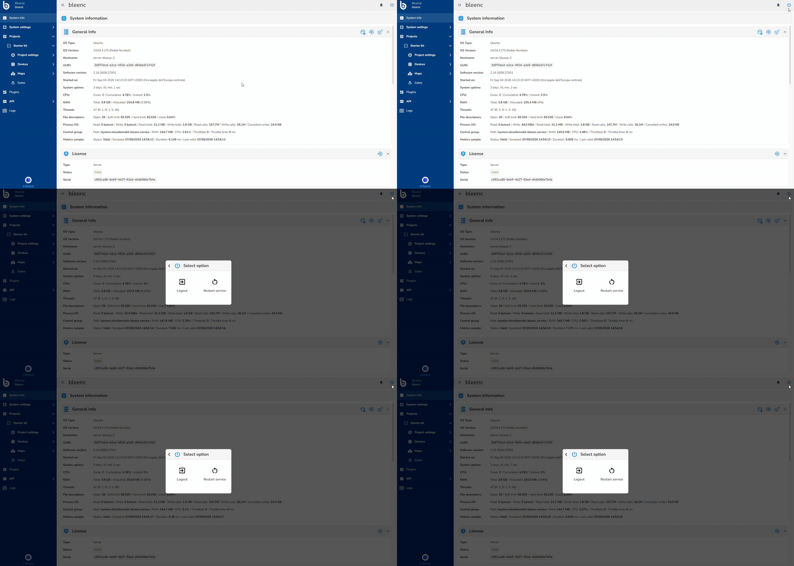
By pressing the  button in the upper-right corner, the system opens a pop-up menu from which it is possible to logout of the system or restart the service.
System Info
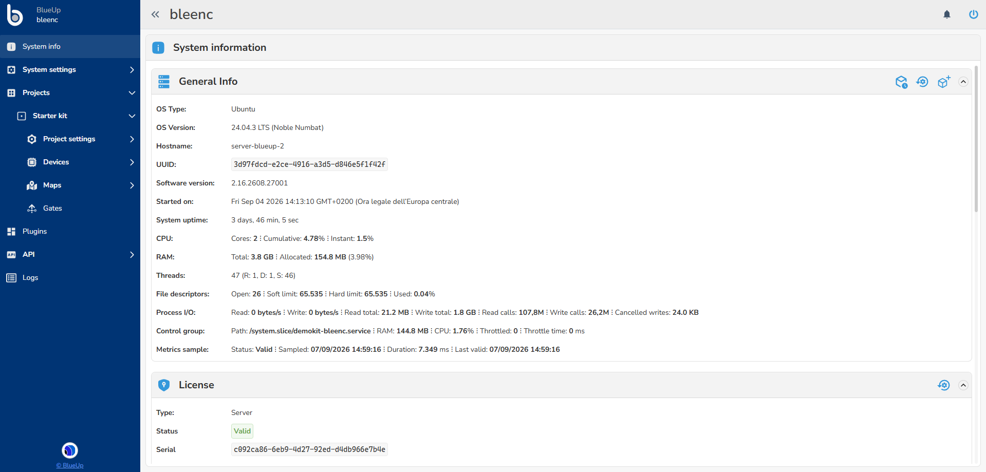
This first tab of the bleenc Web Interface displays all the necessary information about the software, the license and network.
From this interface the user can check if there are new software updates available and to update the software by pressing  button.
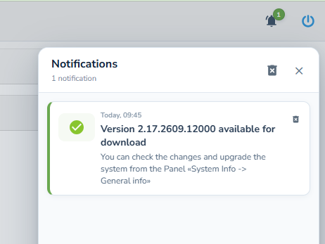
If in software settings the check upgrades is enabled, a notification is raised when there is a new system upgrade available. The notification, unless deleted, remains for 24 hours.
The software upgrade is not automatic and has to be performed by the user.
When pressing on the  button, it is possible to retrieve the changelog of the bleenc versions to track the changes.
License
bleenc is licensed software.
The license is applied to the server on which the service is running.
In System info is summarized the information about the license:
- Status - license current status: Valid or Invalid;
- Expires on - is the expiry date and time of the license;
- Maintenance expiry - is the date and time when the maintenance to bleenc will end. For maintenance is intended the possibility to update the software with the new releases. If the license is still valid, but the maintenance is expired the software can not be updated;
- Capabilities - are the features of the software the user has access to. The user can have a limited license version, without support of some capabilities.
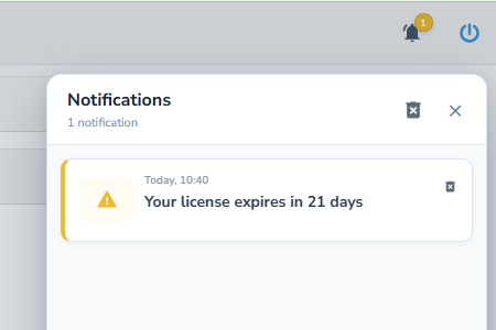
Note: When the license is about to expire, starting from 1 month before the expiry date, the system sends a daily notification to the user to remind to renew the license.
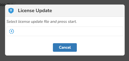
If your license is expired and you have received the new license file, it has to be uploaded by pressing the icon in the License section.
Select and upload the license file you have received to renew the license.
System Settings
This section gathers all the settings of the system: it is divided in subsections where settings and configurations are collected based on their functionality.
System - Timezone
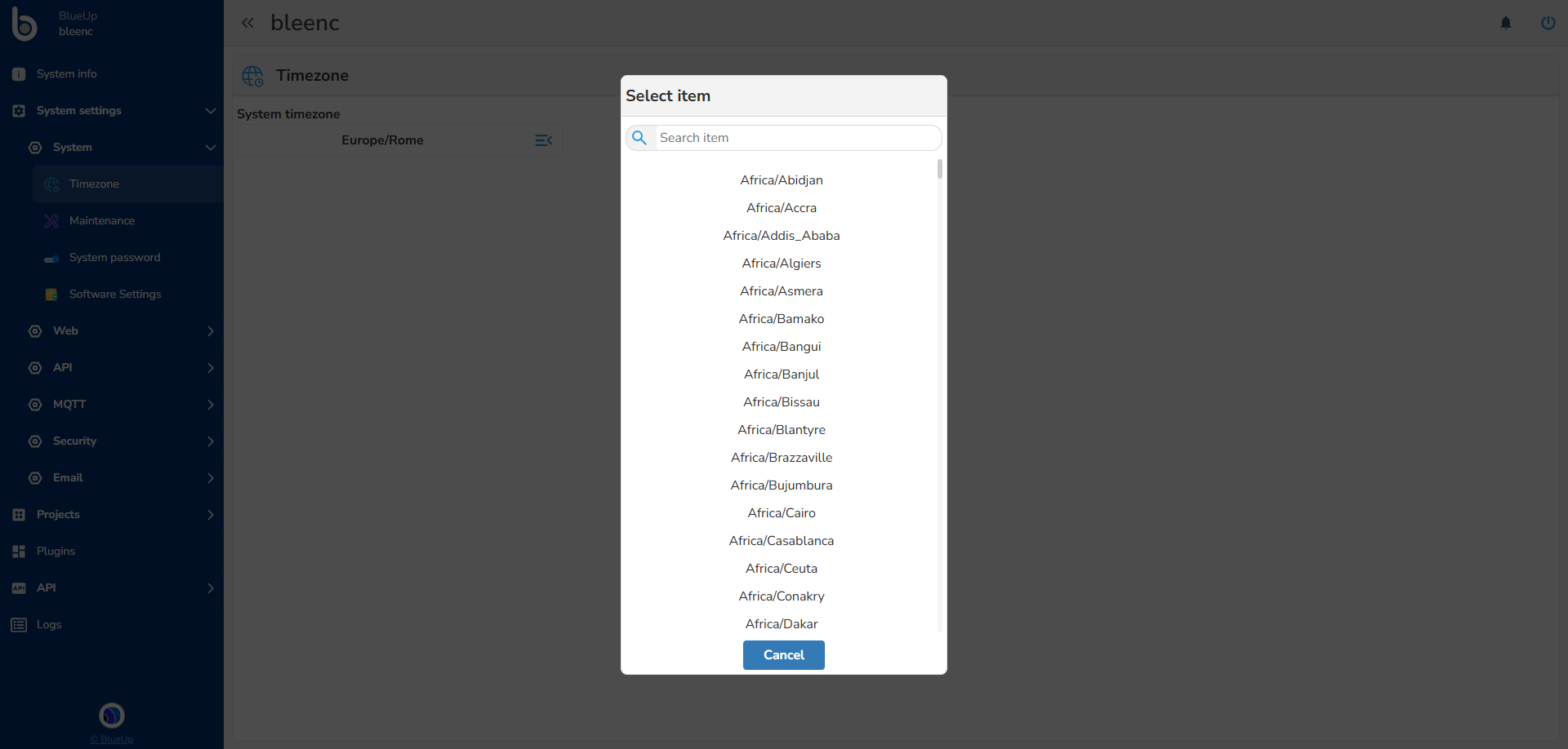
This setting allows to setup the timezone where the system is used. The timezone is useful for Maintenance and other time-related operations.
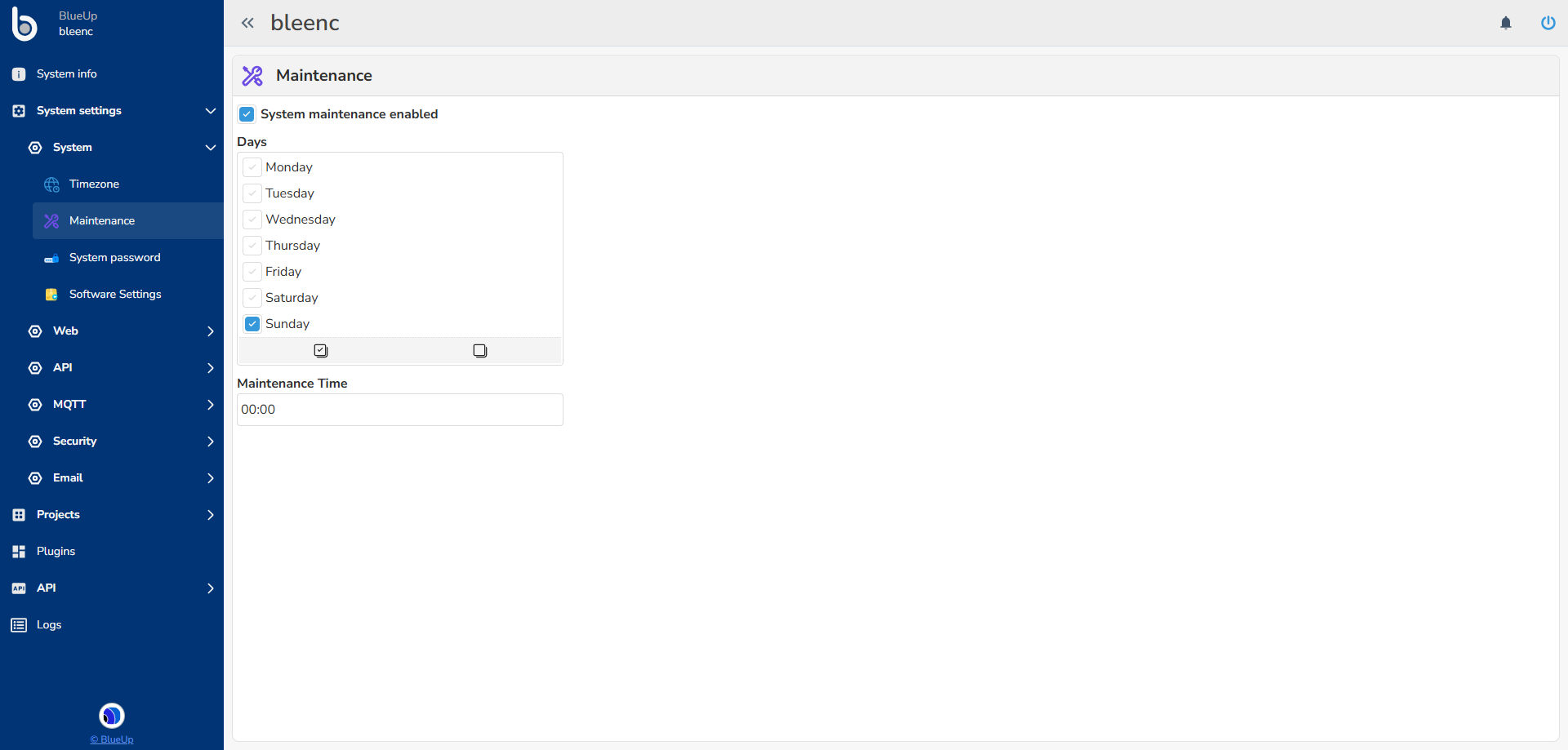
System - Maintenance
This section allows to configure the periodic Maintenance of the system. During maintenance the system performs some operations of checking, optimizing, updating and deleting expired data from the system. During these operations the system can pause some basic functionalities of bleenc.
- System maintenance enabled flag allows to enable or disable system maintenance. It is suggested to keep system maintenance enabled;
- Days - table that allows to select the days when the maintenance will be performed;
- Maintenance Time is the time (in 24h format) when the maintenance is performed.
Since during maintenance some basic functionalities can be paused, when configuring maintenance period it is suggested to set days and time when the system is not used, to not to interfere with system functioning.
System - System Password
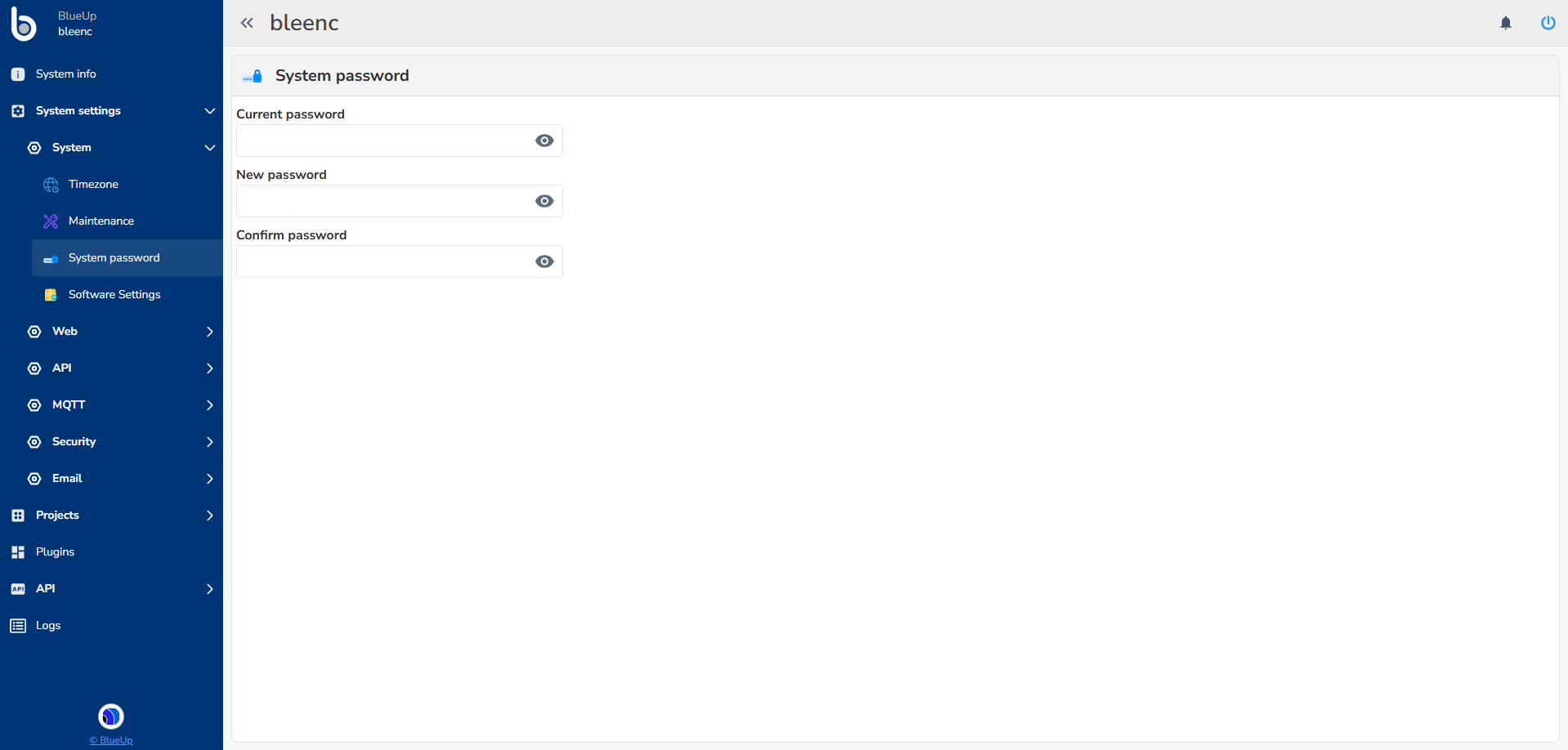
This setting allows to change the access password of bleenc web interface.
After inserting the current password and the new one, the  button will appear to save the new password.
If the New password and the Confirm password do not coincide the button will not appear.
If the inserted Current password is not correct an error pop-up will appear.
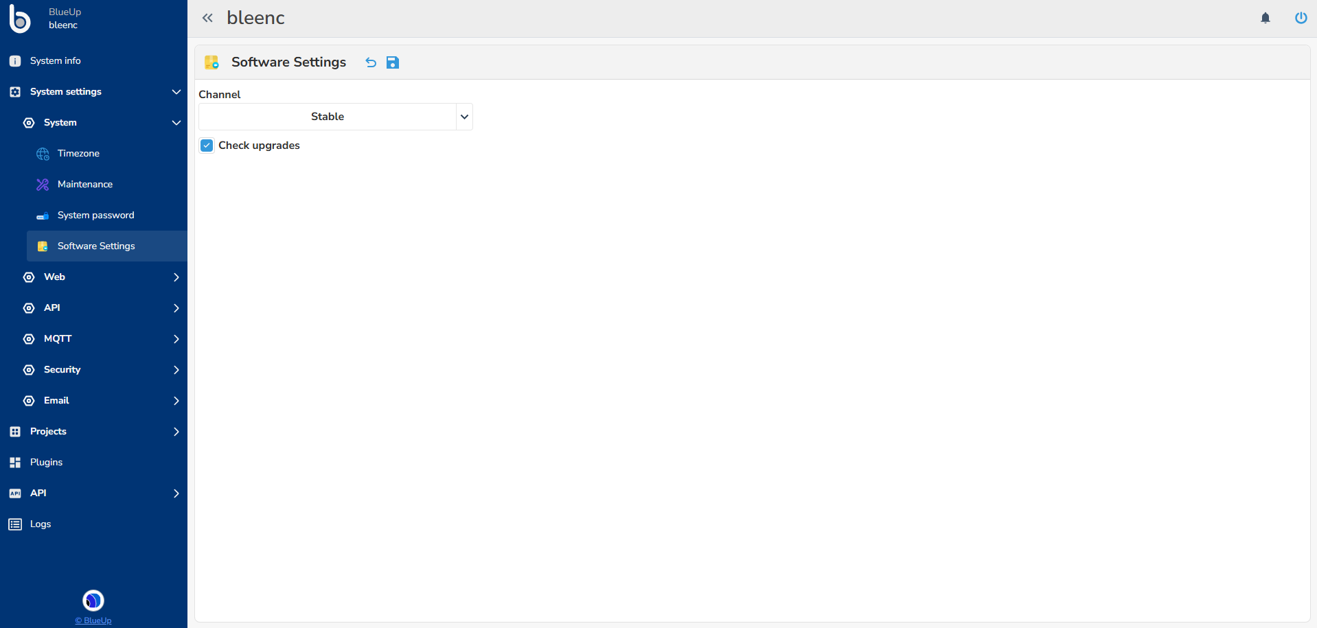
System - Software settings
This setting allows to select which software release to use, among:
- Stable - the officially released version of the software;
- Beta - a Beta version of the software, before stable release;
- Dev - a Development version of the software;
- Custom - available only if a custom version of the software has been required. In this case BlueUp will provide the user also with Repository, App id, App key to insert in the settings to download the updates related to the custom version.
By selecting one of the software releases, when updating the software, it will be updated to the latest available version of the chosen release.
Note: if you choose Beta or Dev versions, consider that they are not stable versions, therefore there can be some bugs in the system. If you find any, please report the bug or problem by opening a ticket or by writing an email to support@blueupbeacons.com
The Check upgrades checkbox allows to enable the automatic check of the new available software upgrades during system maintenance. If a new version is found, a notification will appear in the notify center.
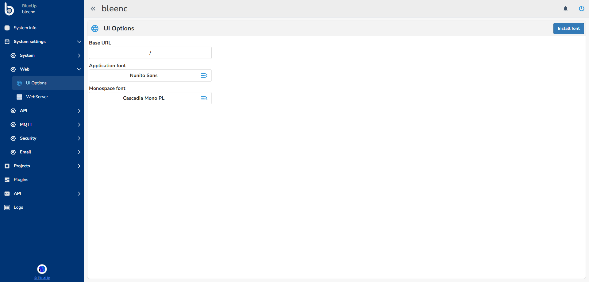
Web - UI Options
The UI option allow to customized the following interface settings:
- Base URL - defines the base path under which the bleenc web interface is served. The default value,
/, serves the interface at the server root. Set a different path, such as/bleenc, to serve it under that path. Changes to Base URL require a system reboot to take effect. - Application font - the main font used for interface text.
- Monospace font - the fixed-width font used for technical values, such as identifiers and code.
The fonts can be selected among the available ones, or other custom fonts can be installed in the system.
Web - WebServer
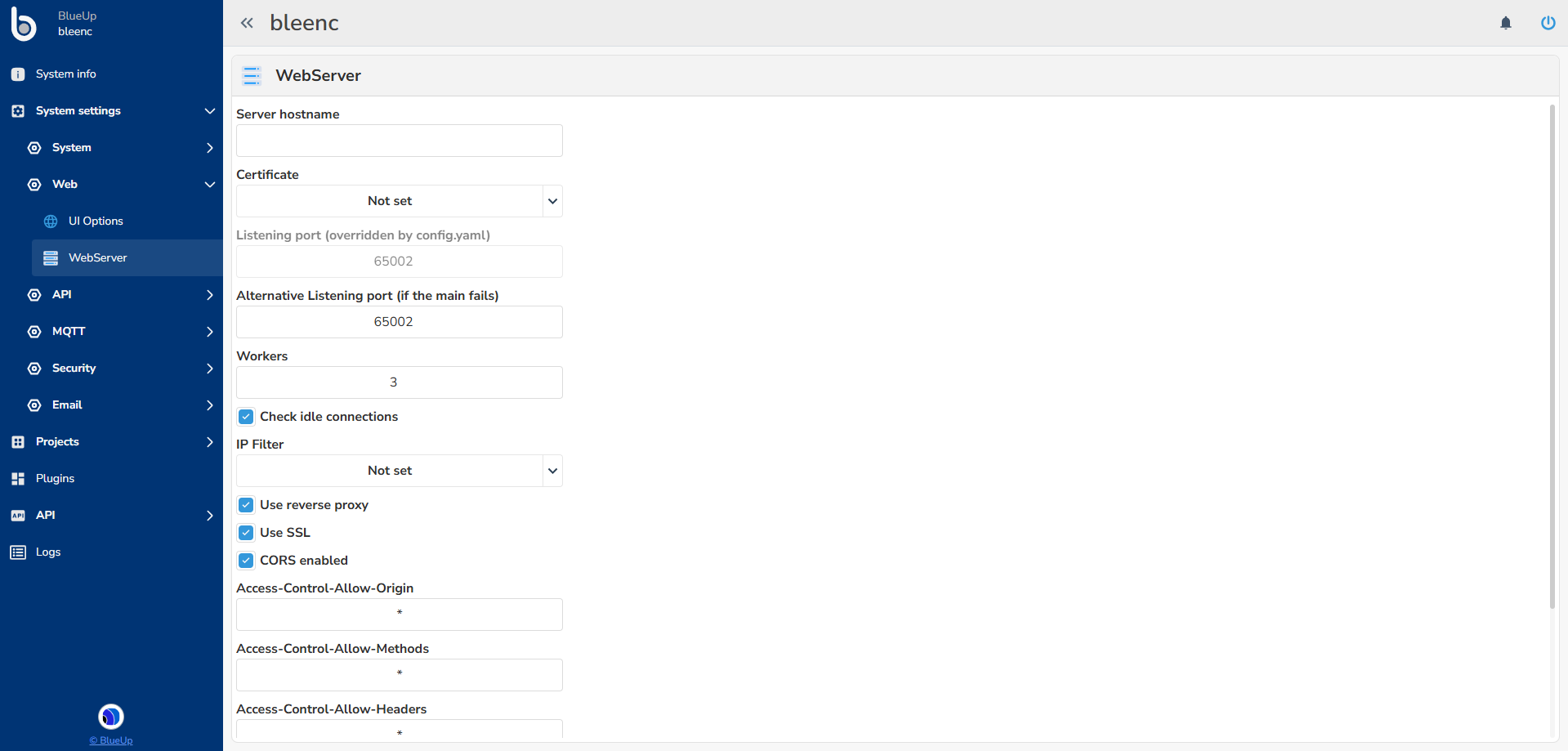
The WebServer settings allow to setup the HTTP/HTTPS server parameters.
- Server URL is used to setup the URL at which the server is reachable;
- Certificate allows to select (in case of HTTP S connection) the certificate corresponding to the HTTPS connection. The certificate is setup in Certificates settings;
- Listening port is the port at which the service is listening;
- Workers is the number of processes that the system can open at the same time;
- Check idle connections is a function that scans for active connections to the server and automatically closes the connections that have been idle for at least 1 hour;
- Use reverse proxy is an advanced setting related to the proxy. Leave to default value if not sure about its use;
- CORS enabled allows to setup the cross calls to the system from other domains. For more information refer to Cross-origin Resource Sharing.
API - API Settings
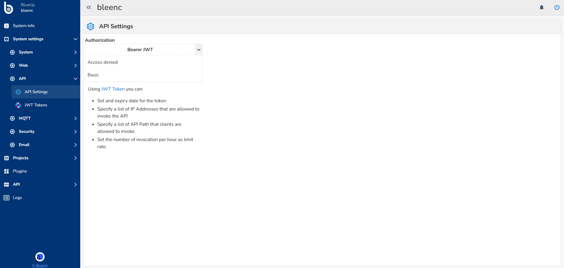
This setting allows to setup the security level for what concerns the HTTP API calls.
- Access denied - is used to disable the calling of APIs;
- Basic - the user has to specify a Username and Password to use when calling the API;
- Bearer JWT - authenticates API requests using a JWT bearer token, described here. To use this modality, the user has to generate a JWT Token in JWT Tokens section.
API - JWT Tokens
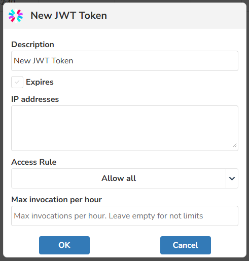
To authenticate using Bearer JWT method, a JWT Token has to be generated to be used when calling an API. To create a new Token press on  and fill in the following fields:
- Description of the JWT token;
- Expires to set or not a Token expiration date. In case this field is checked, the user has to set an expiry date and time;
- IP addresses is the list of IP addresses that can call the APIs. If left blank, all IP addresses will be allowed;
- Access Rule options are:
- Allow all to allow the access to all API calls;
- Allow selected APIs to allow calling only the selected API calls;
- Deny selected APIs to deny calling the selected APIs;
- Allow all to allow the access to all API calls;
- Max invocation per hour is the maximum number of API calls that can be invoked per hour with this JWT token.
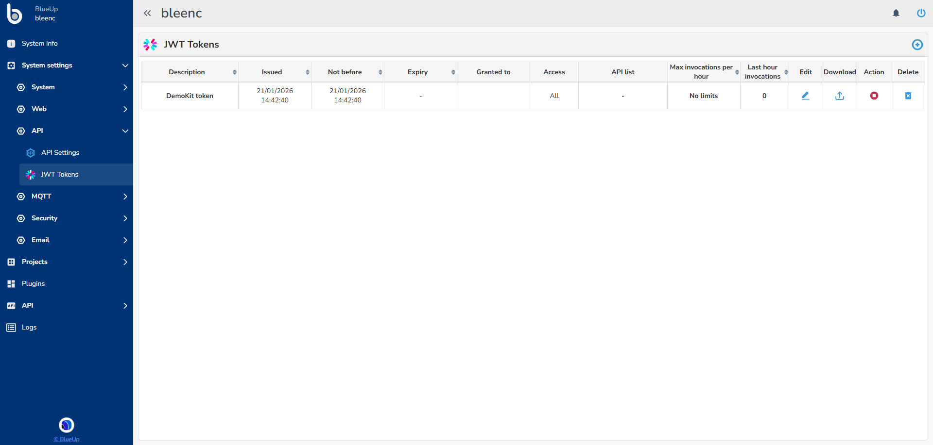
Once that a Token is saved, it will appear in the list of JWT Tokens.
In the table, for each generated JWT Token are summarized the configured parameters.
Additional Token operations are:
 Edit token
 Download token
 Enable or
 Disable token
 Delete token
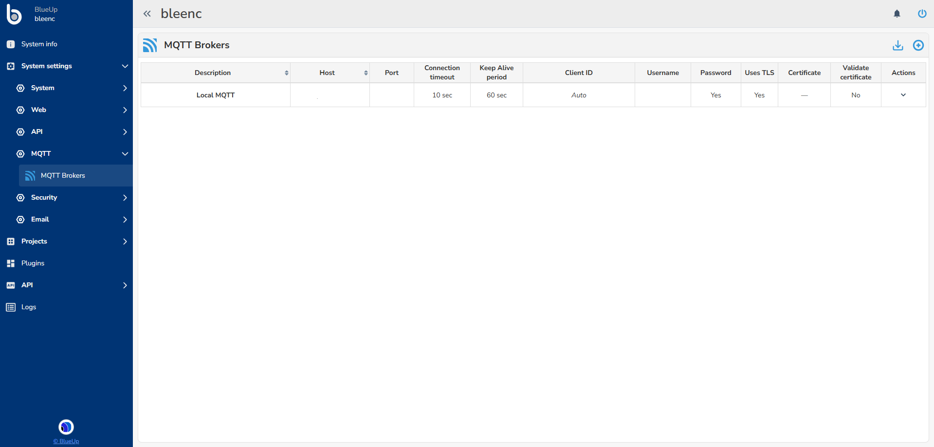
MQTT - MQTT Brokers
In this section is possible to configure the MQTT Broker connections for data transmission. For each MQTT Broker are defined the parameters for the connection to the Broker.
A broker configuration can be imported or created from scratch. Also an existing configuration can be cloned and changed, instead of creating a new one.
Security - Certificates
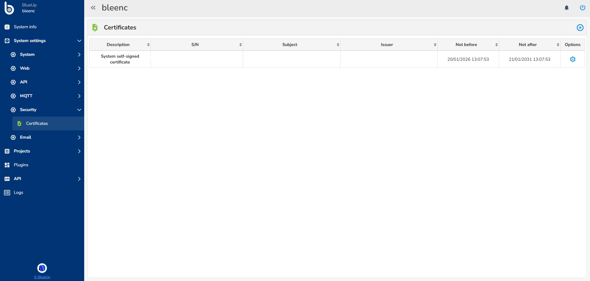
This section allows to upload and store all the certificates that are used for TLS connections.
To upload a certificate, press on the upload button  . The acceptable certificate format is PKCS#12.
Email - SMTP Servers
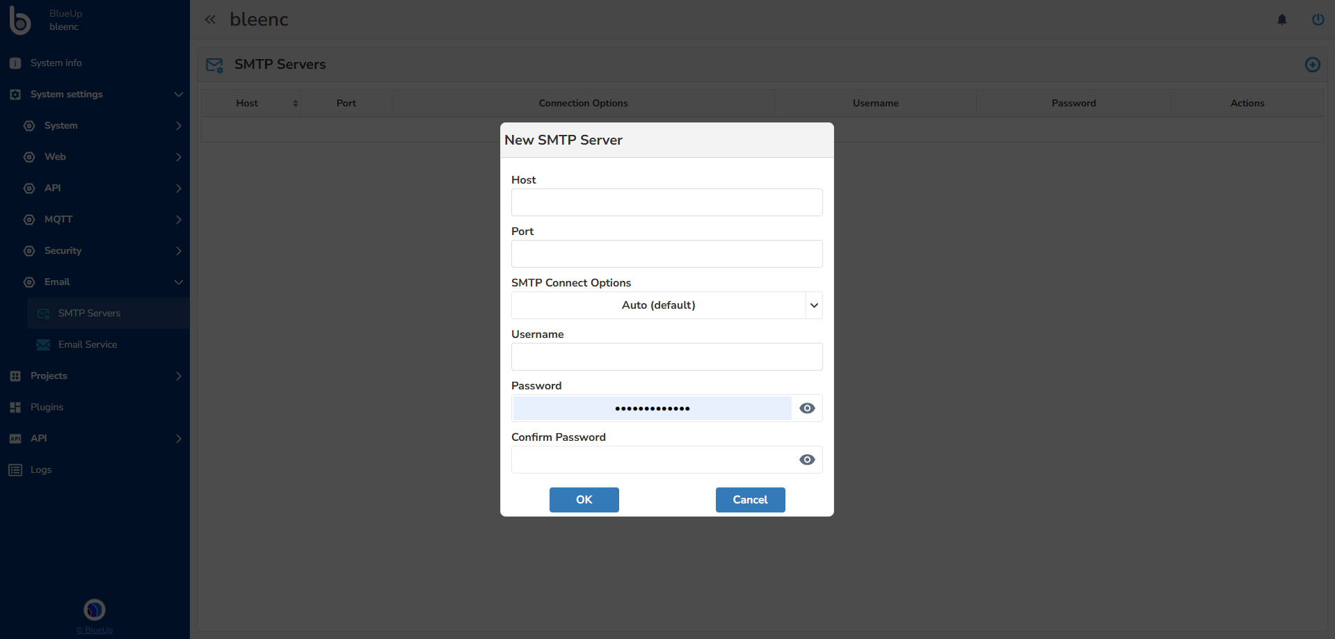
This setting is used to setup SMTP server for the emailing function. When configuring a new SMTP server the fields to fill in are:
- Host
- Port
- SMTP connect options are:
- Auto
- SSL
- TLS
- Auto
- Username
- Password
Email - Email Service
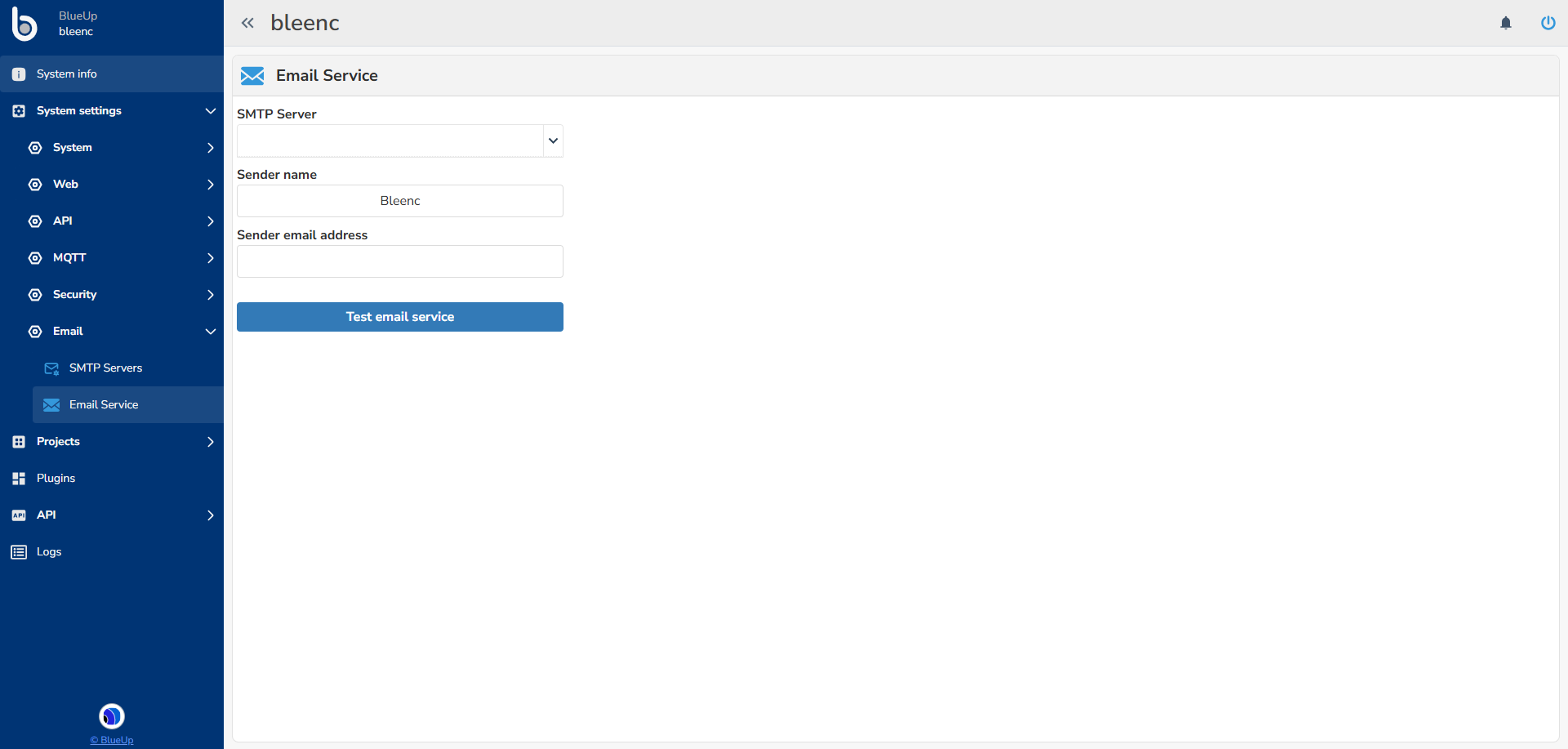
This section can be used to setup an email service. This service can be used for testing purposes or to configure Plug-ins that support email services.
- SMTP Server to be selected among the SMTP servers setup in the previous section;
- Sender name to be able to recognize the email coming from bleenc service;
- Sender email address is the email address from which bleenc will send emails.
Projects
bleenc system can manage multiple projects in the same instance. Each project has its own network parameters, gateway templates, tag class settings and tracking settings.
Separate projects can be used to manage different sites or installations on the same server.
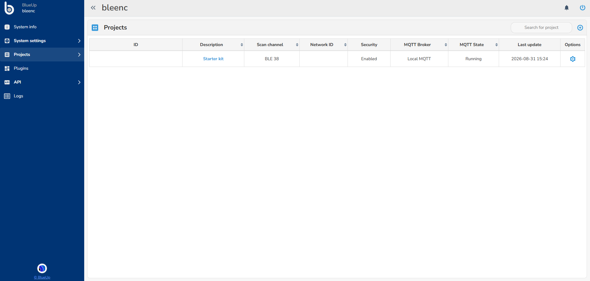
The main interface lists all the projects currently available in the system. For each project the following information is displayed:
- ID - The identifier assigned to the project by the system.
- Description - The project name displayed in the interface. Click it to rename the project.
- Scan channel - The radio channel configured for the project.
- Network ID - The network ID used by the project's devices.
- Security - Whether a security key is configured.
- MQTT Broker - The MQTT broker connection selected for the project.
- MQTT State - The current state of the project's MQTT connection.
- Last update - The last update timestamp reported for the project.
- Options - Access to export, configuration synchronization and removal of a project.
- Sync project configuration - publishes the current bleenc gateway and tag configuration to the MQTT Broker to synchronize it with the instance.
Create a new project
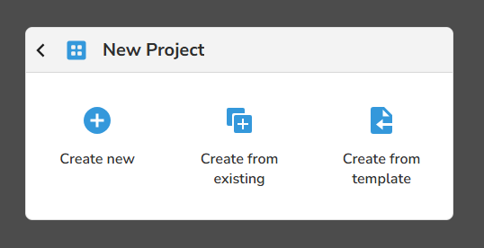
In the upper-right corner of the project list press on to Create new project. The following options are possible:
- Create new: configure a new project from scratch.
- Create from existing: select an existing project and use its configuration as a starting point.
- Create from template: upload a project JSON file previously downloaded using Export.
Enter a Description to name the project. The description is separate from the project ID, which is assigned by the system.
Configure the network and provisioning parameters described under Network Settings. For a new project, bleenc initially generates a Network ID and a security key, selects BLE 37, and fills in default provisioning parameters. Review these values and select the Service Mqtt Broker before saving.
Project statistics
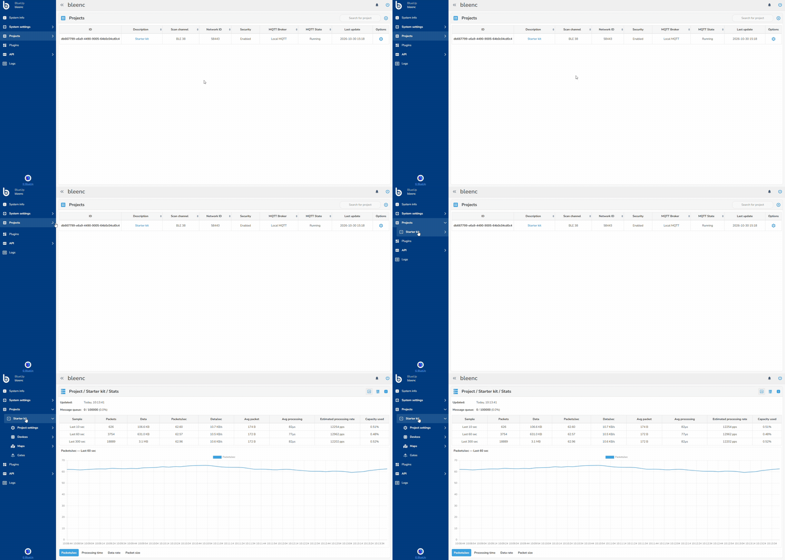
When pressing on the single project menu, under Project, a window with project statistics is displayed.
This view displays MQTT packet processing statistics for the last 10, 60 and 300 seconds, together with the latest statistics update time and the message queue count. When a queue capacity is available, the queue display also shows its capacity and percentage used.
- Sample - The time window used to calculate the statistics.
- Packets / Data - The number of processed MQTT packets and their total size during the sample window.
- Packets/sec / Data/sec - The average packet rate and data rate during the sample window.
- Avg packet - The average MQTT payload size.
- Avg processing - The average message processing time.
- Estimated processing rate - The estimated number of packets that could be processed per second at the current average processing time.
- Capacity used - The current packet rate as a percentage of the estimated processing rate. This value does not represent overall CPU usage.
Charts show packet rate, processing time, data rate and average packet size. They use the 60-second sample and retain five minutes of history for the current session. Click on the  information control for an explanation of the metrics.
Provisioning
Provisioning is a process through which bleenc devices, that are configured in provisioning mode, can be configured to join a bleenc project. A gateway with provisioning enabled handles communication with tags in provisioning mode, using the provisioning parameters configured for the project.
The project provisioning parameters are configured under Network settings:
- Provision - Start address and Provision - End address: define the device address range used by the provisioning process. Each address is entered as eight hexadecimal characters.
- Provision - destination class: defines the class assigned during provisioning, from Class 0 to Class 7. Configure the destination class before provisioning tags.
- Provision - PIN: defines the numeric provisioning PIN. The PIN must match the one configured on the bleenc devices to allow to join the bleenc network.
To enable a gateway to perform provisioning, enable Provisioning in its configuration template and assign that template to the gateway. The Provision indicator in the gateway list shows whether provisioning is enabled in the reported configuration.
Before provisioning a tag, check the project's network and provisioning settings, ensure that the destination class is configured, and place the tag within radio coverage of a gateway with provisioning enabled. After provisioning, verify that the tag appears in the intended project and reports the expected class and configuration status.
Note: The Provision command restarts the tag in provisioning mode. Successful execution of this command does not, by itself, confirm that provisioning has completed.
Project Settings
Project settings menu is divided into sections allowing the project configuration.
Network Settings
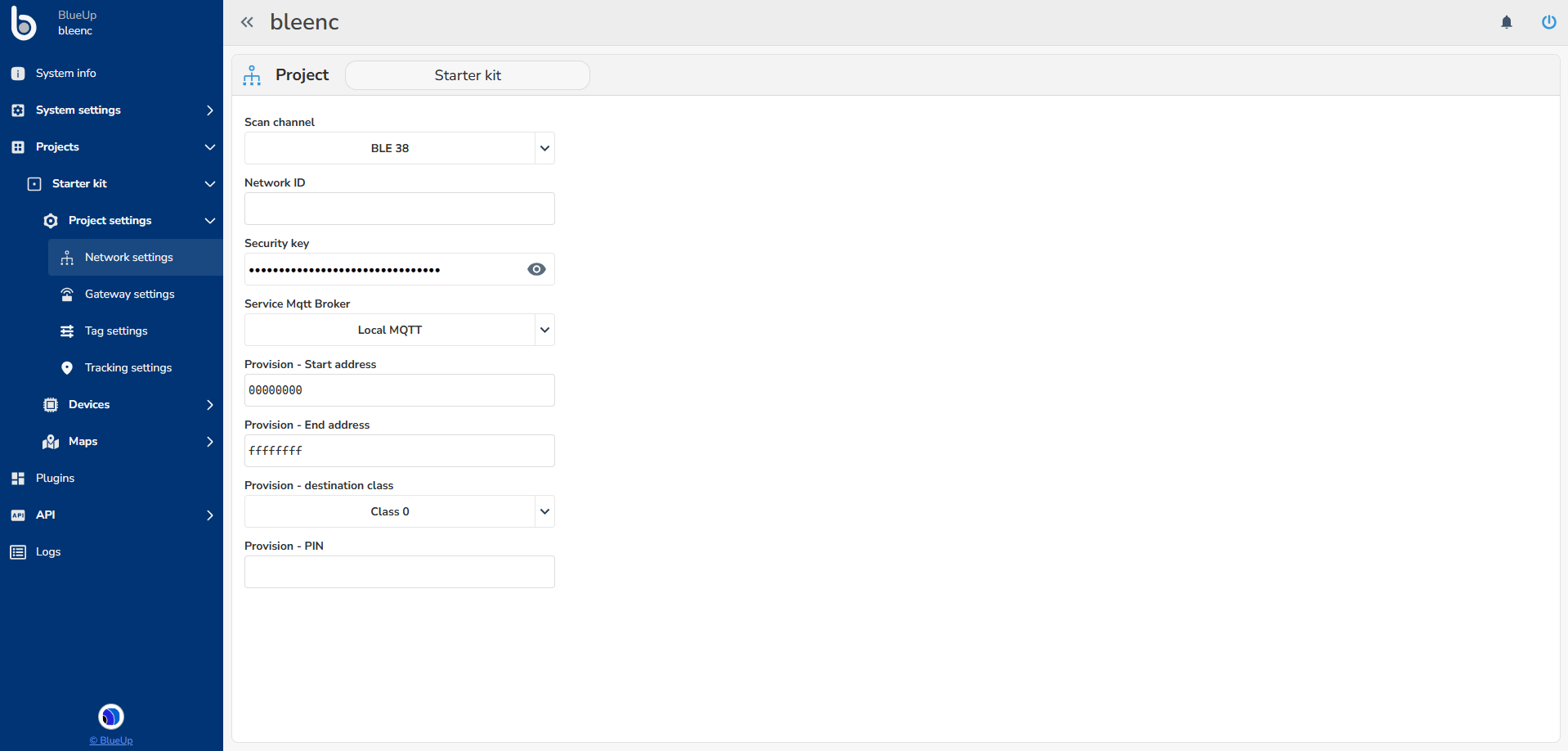
Network Settings allows to edit the project's network and provisioning parameters. The same parameters are requested when creating a project.
- Description - to set or change the project description.
- Scan channel - Select BLE 37, BLE 38, BLE 39, or one of the 3 Proprietary channels, according to the device configuration.
- Network ID - The numeric network identifier.
- Security key - A 16-byte key entered as 32 hexadecimal characters. Saving without a valid key opens a Security Disabled warning and requires explicit confirmation to continue without security features.
- Service Mqtt Broker - Select a connection defined under System Settings - MQTT Brokers.
- Provision - Start address - The start of the device address range used for provisioning. The default is
00000000. - Provision - End address - The end of the device address range used for provisioning. The default is
ffffffff. - Provision - destination class - The class assigned during provisioning, from Class 0 to Class 7.
- Provision - PIN - The numeric provisioning PIN, displayed with six digits. The PIN has to match the one configured on the devices to provision.
Warning: Network and provisioning parameters must match the devices used in the installation. Changing them on an operational project may interrupt communication with gateways and tags.
Gateway Settings
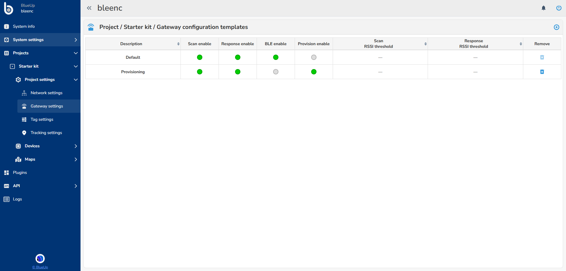
Gateway settings menu allows the creation of configuration templates to apply to the gateways.
Press on in the upper right corner to create a new template, or press on the template row to modify it.
The template defines the gateway's behavior. The configuration parameters are:
- Enable / Disable scanning - to enable gateways to scan for bleenc devices. Configure it as enabled for correct system functioning;
- when scanning is enabled, optionally is possible to enable and setup the scan RSSI threshold
- Enable / Disable response - to enable gateways to send commands to bleenc tags;
- when response is enabled, optionally is possible to enable and setup the response RSSI threshold;
- Enable / Disable BLE whitelist - to enable bleenc gateways to scan for BLE devices;
- Enable / Disable provisioning - to enable the gateway to provision new devices.
Gateway template is assigned to the gateways in Gateways section.
Tag Settings
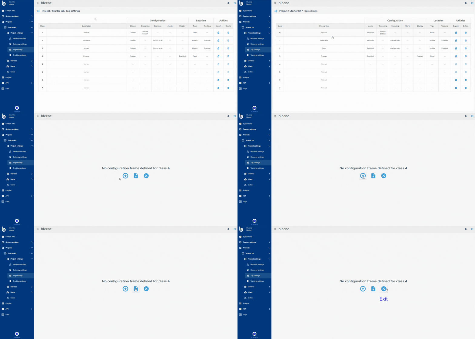
Every project can have up to 8 different tag classes, each configured differently for every requirement.
The Tag settings table summarizes the class configurations defined in the project.
To enter the class configuration menu press on the row of the class to configure.
If the class configuration is not defined yet, it is possible to:
- add new configuration frame; or
- import a configuration file.
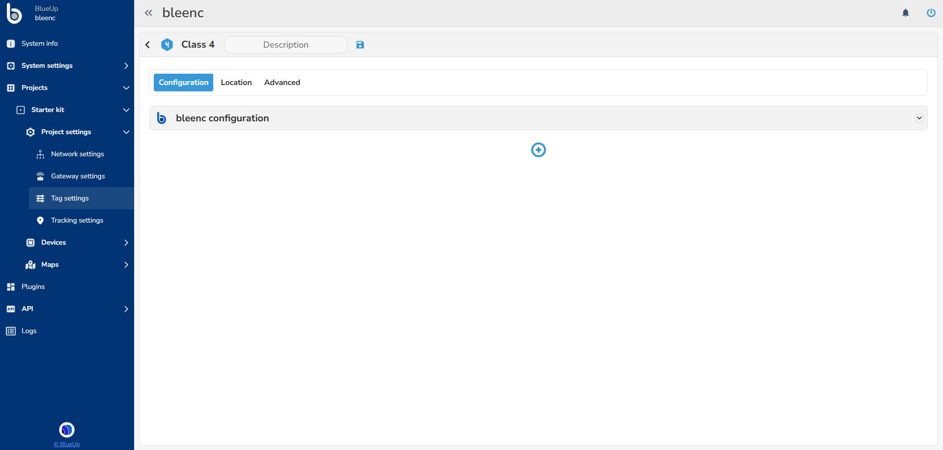
Each class configuration has a Description, that has to be set before saving the configuration, and the configuration is divided into 3 sections:
- Configuration
- Location
- Advanced
Configuration
The Configuration section allows to setup the tag's configuration frames. The possible configuration frames are:
- bleenc configuration - base bleenc configuration frame, that is always present in the tag's configuration and cannot be deleted;
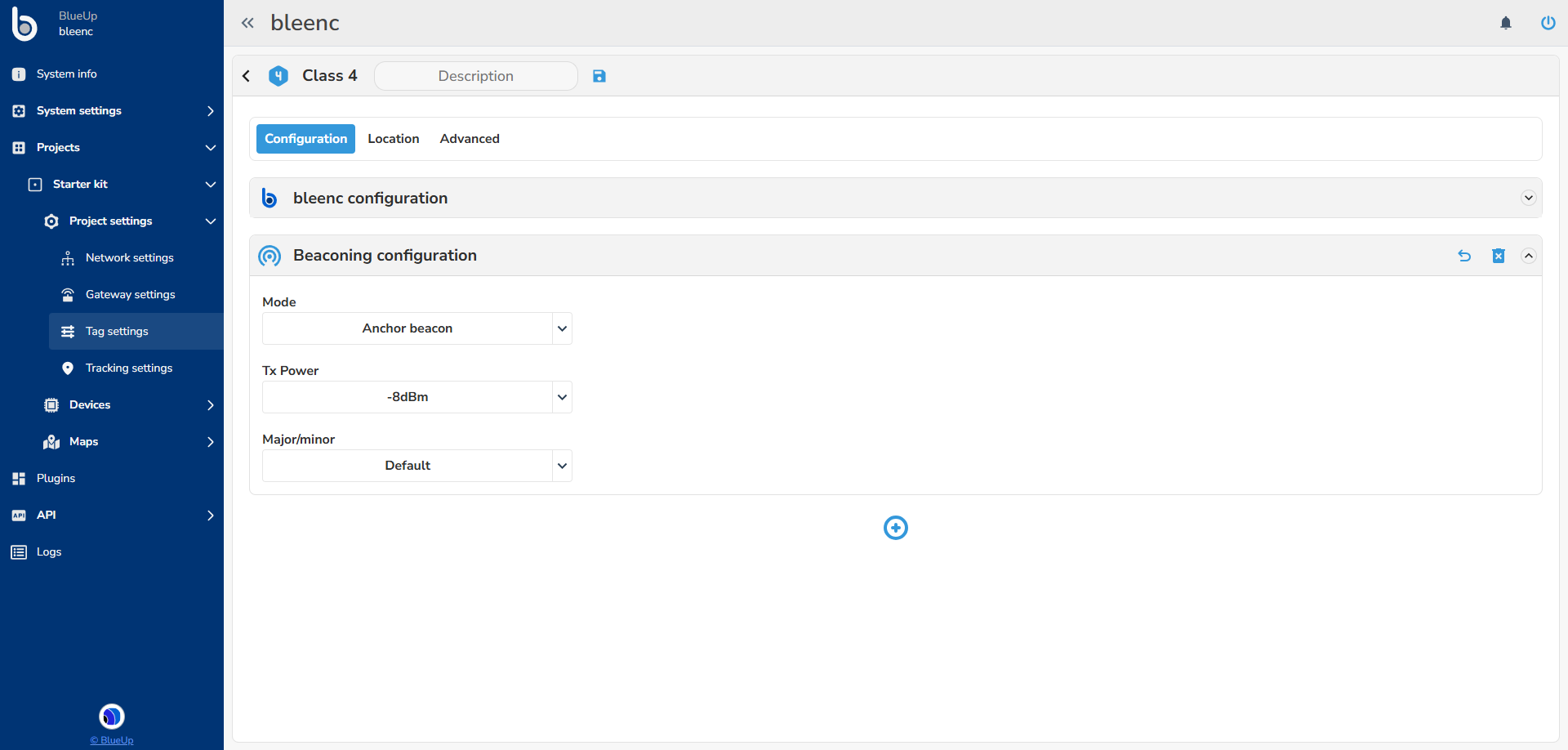
- Beaconing configuration - allows to configure beacon advertising parameters;
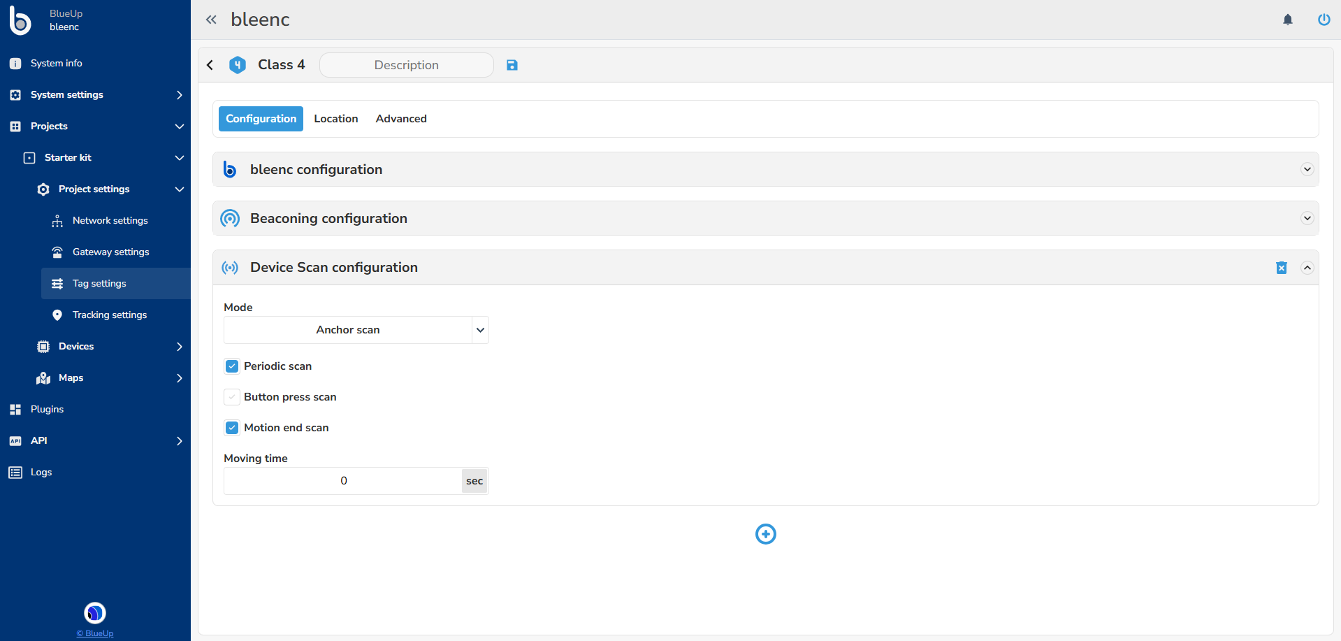
- Device Scan configuration - to configure the device scanning functionality;
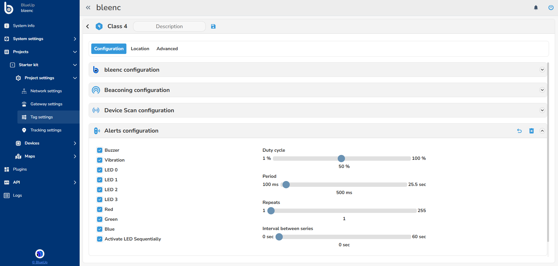
- Alerts configuration - to configure permanent alarm on the tags;
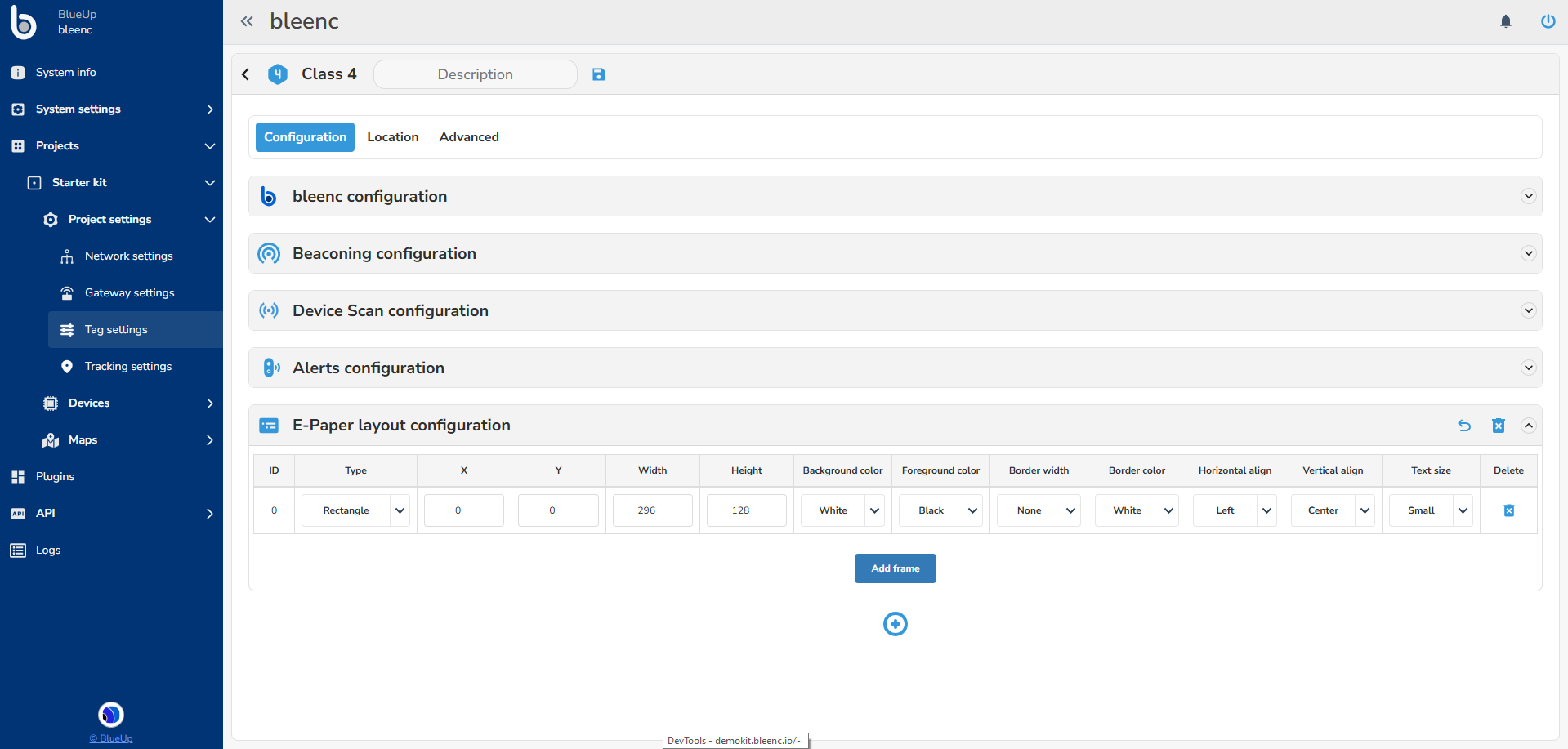
- E-Paper layout configuration - to configure the layout of the display of the E-Paper.
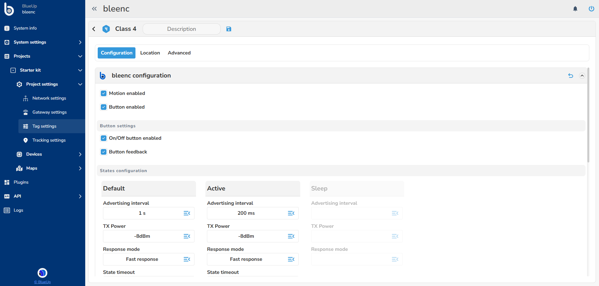
bleenc configuration
The configuration parameters of bleenc frame are described below.
- Motion enabled, allows to enable or disable motion detection;
- Button enabled, if mounted, allows to enable and disable the button pressure;
- Button settings, if the button is enabled:
- On/Off button enabled allows to turn off and turn on the tag with the button pressure;
- Button feedback allows to enable feedback/acknowledgement when the button is pressed;
-
States configuration: a bleenc tag can have three working states, that are Default, Active and Sleep. The configuration parameters, common for all the states are:
- Advertising interval;
- TX Power;
- Response mode;
-
State timeout - how long the tags remain in that state, before switching to default or to sleep state. In Active state, the timeout has to be greater than 0.
A tag can enter Active state if:- Motion is enabled and the tag is moving, or
- Button is enabled and the button is pressed.
-
Motion detection parameters are:
- Motion threshold defines the intensity of movement. Acceleration needs to be greater than the threshold to detect movement.
- Motion duration defines the minimum time period for which the acceleration must be greater than the threshold to detect movement;
- No Motion to raise an alarm when the tag has not been moving for the configurable time;
- Advanced detection allows to configure advanced functionalities, other than motion detection. Each accelerometer functionality has its own configurable parameters. Other Accelerometer modes are:
- Tilt
- Freefall
- Shock
- Mandown is the additional functionality that can be enabled together with the previous detection modes.
- Other settings:
- Led/Buzzer/Vibration to enable or disable the alerts on the tag;
- Calibrated RSSI offset 1mt.
Beaconing Configuration
The bleenc positioning system can operate at two complementary levels: real-time positioning through gateways and periodic or event-triggered positioning through fixed anchors. The second method requires fixed devices configured to transmit beacon packets and mobile tags configured to scan for those packets.
Therefore, the Beaconing Configuration and Device Scan Configuration settings must be configured consistently when this positioning method is used.
Beaconing Configuration defines how bleenc devices transmit BLE advertising packets. The following options are available:
- Anchor beacon: the default and recommended option for fixed devices used as reference points for periodic or event-triggered positioning. When this option is selected, the corresponding mobile tag class must be configured as Anchor scan under Device Scan Configuration. The advertising interval and UUID are set automatically to the required default values, while the TX power and Major/Minor value management remain configurable.
- Custom beacon: allows the advertising packet to be configured manually for positioning or other BLE-based applications. The supported advertising formats are:
- iBeacon,
- Eddystone-UID,
- Quuppa AoA, and
- BlueUp AoA.
The available parameters depend on the selected format.
Device Scan Configuration
Device Scan Configuration defines how mobile tags scan for BLE packets transmitted by fixed devices. For periodic or event-triggered positioning, this setting must be used together with Beaconing Configuration.
If the fixed devices are configured as Anchor beacon, select Anchor scan for the mobile tag class. Alternatively, Custom scan can be used to manually configure the tag to scan for iBeacon or bleenc packets.
Scanning can be triggered using the following options:
- Periodic scan: performs a scan at a configurable fixed interval.
- Button press scan: performs a scan when the button on the tag is pressed.
- Motion end scan: performs a scan when the tag stops after having been in motion for at least the configured Moving time.
Alerts configuration
Alert configuration allows to configure a persistent alert on the tag.
The alert can use a combination of buzzer, vibration motor, and LED, withe a configurable duty cycle, period, number of repetitions, and interval between alert sequences.
E-Paper layout configuration
Please check the display resolution before configuring it.
The display can be divided into up to 16 frames, each one can be configured as:
- rectangle
- text
- QR code
- Barcode
- Icon
For each frame, both background and foreground colors can be selected, if available for the device. Alignment and text size are also configurable.
The frames can be arranged freely on the display, taking special care in defining the origin (x, y), width and height of each frame.
Make sure that the frames are non overlapping, for tag’s correct configuration and update.
Location
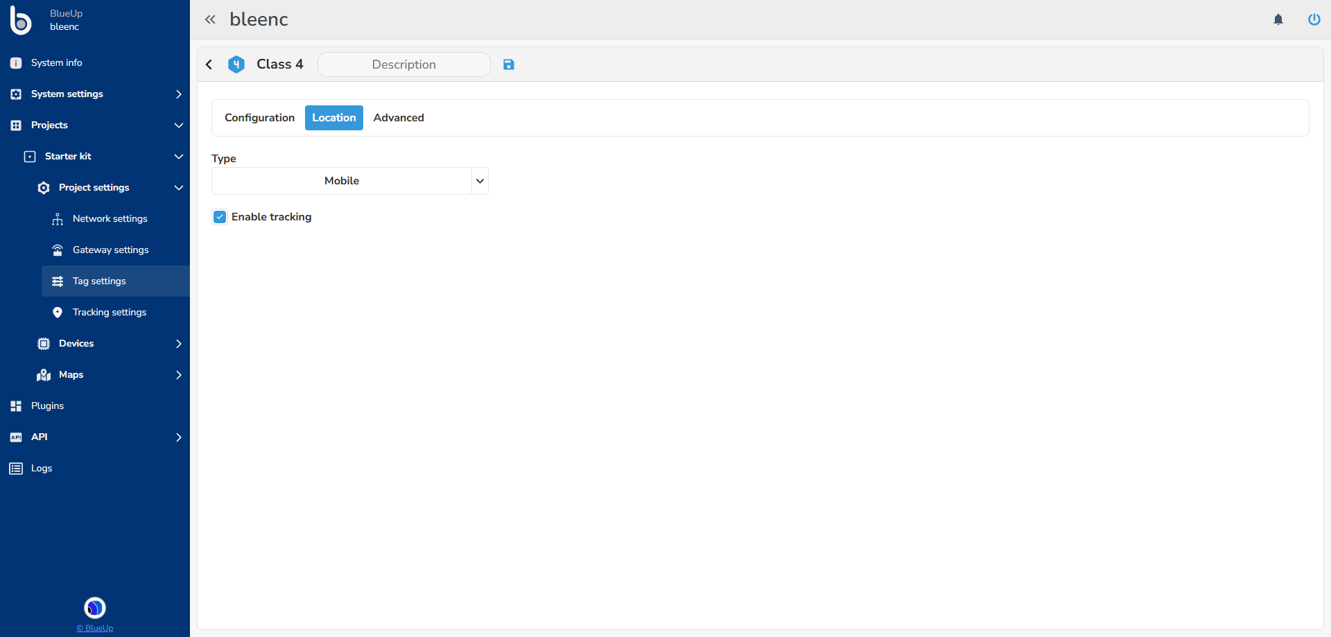
Location configuration tab allows to:
- select if the devices of that class are fixed or mobile;
- in case of mobile tags, the system allows to configure whether to track the devices. For Fixed tags the tracking is disabled by default.
Advanced
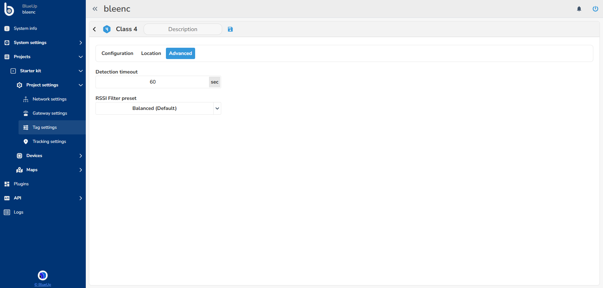
Advanced tab has 2 configuration parameters:
- Detection timeout is the time interval after which the receiver is considered expired. If the tag has no active receivers, then the tag goes offline.
- RSSI Filter preset sets up the Kalman filter parameters for filtering the RSSI signal between the tag and the gateway.
Tracking Settings
The Tracking Settings section contains the positioning and proximity configurations applied to the current project. It includes settings for Real-time tracking, Snapshot tracking, and Proximity.
A tag can have different types of position. Mobile tag positions can be calculated in real time from data collected by gateways or upon receipt of a scan packet containing the fixed beacons detected by the tag.
Fixed tags can instead be assigned a static position manually. A static position has priority over positioning and prevents both real-time and snapshot algorithms from updating the tag location.
Proximity is calculated separately and does not represent the tag position. It indicates the level of proximity between a tag and a gateway or receiver based on the measured RSSI attenuation and the configured thresholds.
Real-time Tracking
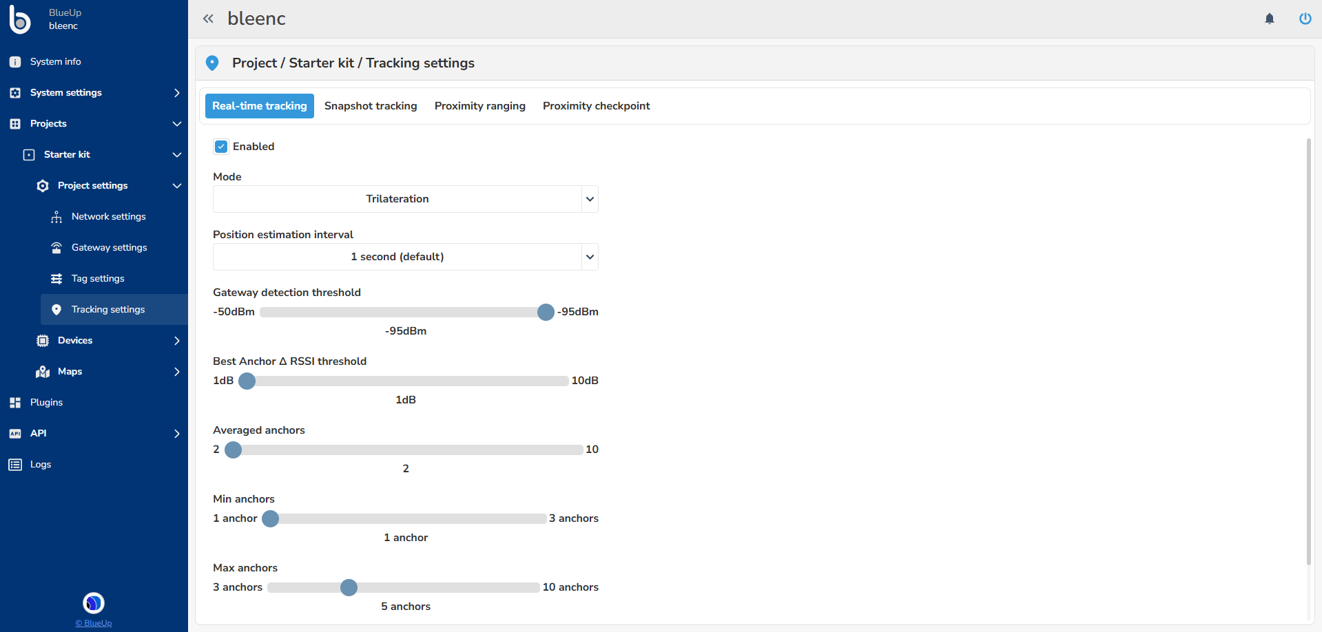
Real-time tracking periodically estimates the position of mobile tags using the signals received from the gateways. The available positioning mode is Trilateration.
The real-time tracking configuration parameters are:
- Enabled: enables or disables real-time tracking for the project. It can be disabled when real-time positioning is not required.
- Mode: defines the positioning algorithm. The only available mode is Trilateration.
- Position estimation interval: defines how frequently the tag position is calculated. The available values are 1, 5, 10, 15, 30, and 60 seconds.
- Detection threshold: defines the minimum RSSI value required for an anchor to be included in the position calculation. If the RSSI between the tag and an anchor is below the configured threshold, that anchor is excluded.
- Best anchor delta: defines the minimum RSSI difference required to select one map over another when the tag is detected by anchors associated with multiple maps. A higher value requires a clearer signal difference before the system switches to or selects another map.
- Averaged anchors: defines the number of anchors used to calculate the average RSSI for each candidate map when the strongest signals alone do not meet the Best anchor delta threshold. The system compares these averages to select a map.
- Min. Anchors: defines the minimum number of eligible anchors required to calculate the tag position.
- Max. Anchors: defines the maximum number of anchors used in the calculation. If more anchors are available, only those with the strongest RSSI values are considered.
- Motion threshold: when enabled, prevents minor position variations from updating the displayed position. The position is updated only when the distance between the previous and newly estimated positions is equal to or greater than the configured threshold.
Snapshot tracking - Zoning
Snapshot tracking - Zoning is performed whenever a mobile tag sends a scan packet and the snapshot tracking mode is set to Zoning. The system evaluates the fixed beacons detected by the mobile tag and uses the beacon with the strongest normalized RSSI to determine the relevant map. Only fixed beacons with a static position, an assigned zone, and an RSSI above the configured threshold are considered.
The tag is associated with the zone of the strongest beacon. If other eligible beacons have similar RSSI values, their zones may also be included, allowing the snapshot position to contain multiple zones. If the scan contains no valid beacons, the current snapshot position is removed.
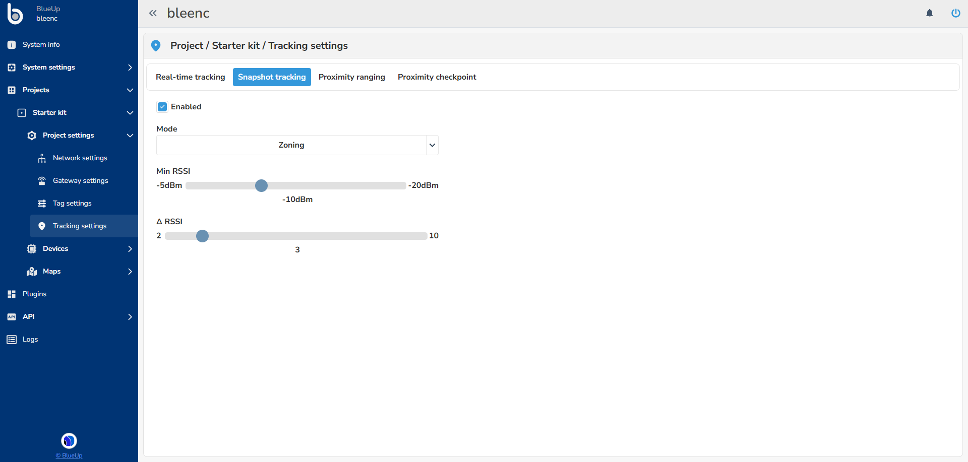
The zoning configuration parameters are:
- Enabled: enables or disables snapshot tracking for the project.
- Mode: defines the snapshot positioning algorithm. Select Zoning to determine the tag position according to the zones assigned to the detected fixed beacons.
- Min RSSI: defines the minimum normalized RSSI required to accept the identified map and include a fixed beacon in the zoning calculation. Beacons below this threshold are excluded.
- Delta RSSI: defines the maximum permitted difference between the normalized RSSI of the strongest beacon and that of any additional beacon. If the difference is equal to or lower than the configured value, the additional beacon’s zone is also included.
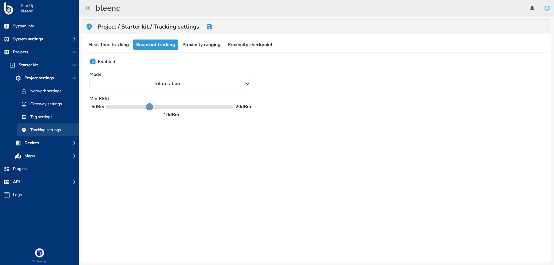
Snapshot tracking - Trilateration
Snapshot tracking - Trilateration is performed whenever a mobile tag sends a scan packet and the snapshot tracking mode is set to Trilateration. The system evaluates the fixed beacons detected by the mobile tag and uses the beacon with the strongest normalized RSSI to determine the relevant map.
Only fixed beacons located on that map, provided with a static position, and detected above the configured RSSI threshold are included in the position calculation. The tag position is then estimated using a weighted average of the eligible beacon positions, with stronger signals having greater influence on the result.
If the scan contains no valid beacons, the current snapshot position is removed.
The trilateration configuration parameters are:
- Enabled: enables or disables snapshot tracking for the project.
- Mode: defines the snapshot positioning algorithm. Select Trilateration.
- Min. RSSI: defines the minimum normalized RSSI required to accept the identified map and include a fixed beacon in the weighted position calculation. Beacons below this threshold are excluded.
Proximity ranging
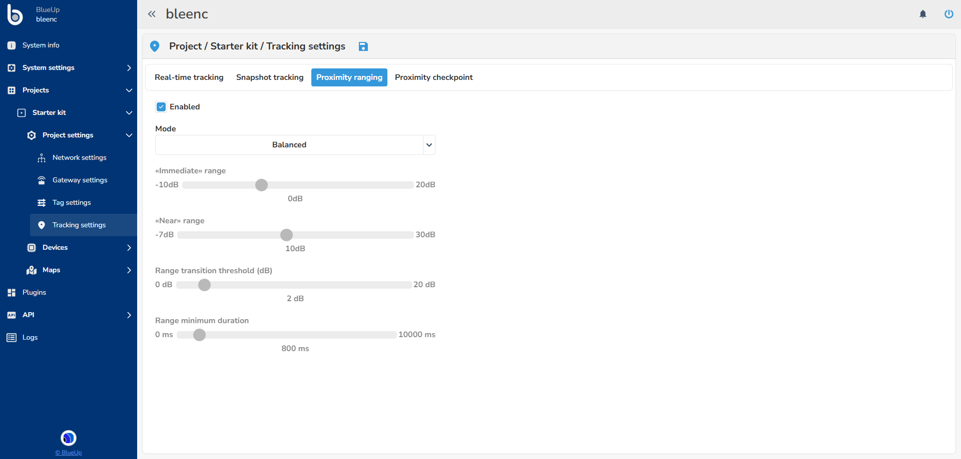
The Proximity ranging function determines the level of proximity between a tag and a receiver. It does not estimate the distance in metres; instead, it processes the received signal and assigns one of the following states: Immediate, Near, or Far.
Signal filtering and stabilization mechanisms are applied to reduce fluctuations and prevent frequent state changes caused by temporary variations in the radio signal.
The proximity configuration parameters are:
- Enabled: enables or disables proximity detection for the project.
- Mode: selects the filter preset used to calculate the proximity state. The available presets are:
- Fast: provides faster and more responsive state changes;
- Balanced: provides a balance between responsiveness and stability and is the recommended default setting;
- Stable: prioritizes stability and reduces state changes;
- Noisy: intended for environments subject to significant radio interference or signal fluctuations;
- Custom: allows the filter parameters to be configured manually.
For predefined modes, the corresponding filter parameters are displayed as read-only values. When Custom is selected, the following parameters become configurable:
- Immediate: attenuation threshold below which the tag is classified as immediately close to the receiver.
- Near: attenuation threshold below which the tag is classified as near the receiver. Values above this threshold result in the Far state.
- Transition: minimum attenuation variation required to allow a change of proximity state.
- Hysteresis: minimum time that must elapse after a state change before another transition is allowed.
Proximity checkpoint
Proximity checkpoint determines whether a mobile tag is within a configured radio proximity threshold of a gateway. The state is evaluated independently for each tag–gateway pair using the difference between the tag's calibrated RSSI and the gateway's normalized, filtered RSSI, referred to as attenuation. Lower attenuation indicates a stronger signal.
The checkpoint becomes On when attenuation remains below the configured threshold for the specified duration, and Off when it remains above the threshold for that duration. State changes are confirmed when new RSSI samples arrive; elapsed time alone does not trigger a change.
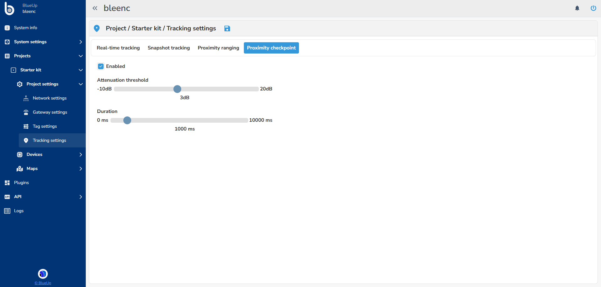
The proximity checkpoint configuration parameters are:
- Enabled: enables or disables proximity checkpoint for the project. It is disabled by default.
- Attenuation threshold: defines the attenuation boundary, in dB, used to determine the checkpoint state. Attenuation below this value corresponds to On; attenuation above it corresponds to Off. A value exactly equal to the threshold does not establish a new state.
- Duration: defines how long a candidate state must persist before the checkpoint state changes. This prevents brief signal fluctuations from triggering a transition.
Individual gateways can override these parameters through Proximity checkpoint settings. Enable Override project settings to configure or disable the checkpoint for a specific gateway, independently of the project-level setting.
Devices
The Devices menu contains information about gateways and tags of the project.
The tables update as device information is received. A dash indicates that a value is not available. Devices loaded from the system cache are displayed in grey; their stored information should not be treated as a current device report.
Gateways
The Gateways page lists the gateways associated with the selected project, with the related information:
- ID - The gateway identifier.
- Model - The gateway model, such as Ethernet, Wifi or Flex.
- Versions - Firmware (FW), bootloader (BL), web interface (UI) and operating system (OS) versions, when available.
- Alias - An optional name used to identify the gateway. Click the cell to edit it, or leave the alias empty to remove it.
- Location - The gateway's position, in case it has been placed on the map, including the map, zone or zones, and X/Y coordinates when available.
- Status - The reported operating status: Running, Idle or Error. Hover over the indicator to read its status.
- Configuration - The assigned gateway configuration template. Click the cell to select another template defined in Gateway Settings.
- Scan, Response, BLE, Provision, DFU - Indicators for scanning, responses to tags, the BLE whitelist, provisioning and Device Firmware Update functionality, as per the selected Configuration template. Green indicates an enabled function; grey indicates a disabled function or unavailable information.
- Scan RSSI threshold / Response RSSI threshold - The configured signal strength thresholds, in dBm.
- IP Address - The retrieved IP address of the gateway.
- Packet/s - The reported packet rate.
- Last boot - The last gateway boot time.
- Options - Access to gateway actions and settings.
Offline gateways have a light-red row background. Gateways loaded from the system cache have a grey background and muted contents.
In the upper-right corner the  Gateway configuration button allows to download the gateway configuration, that can be uploaded on the gateway for an offline gateway setup.

Gateway options
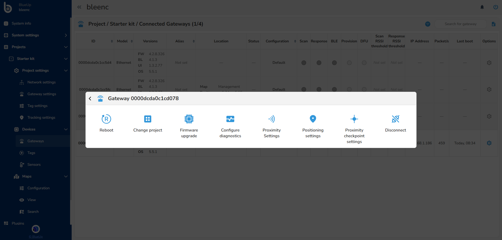
Click Open Gateway options in the gateway's row. The possible options are:
- Reboot - Reboot the gateway.
- Change project - Select another project and confirm the move. bleenc updates the gateway's connection configuration and reboots it to join the destination project.
- Firmware upgrade - Check for available updates. If updates are available, review the listed Device FW, bleenc FW and UI versions, then click Upgrade.
- Configure diagnostics - Enable or disable the core dump reporting. When core dump reporting is enabled, crash dump files may be uploaded to BlueUp servers for debugging and support if the gateway has outbound Internet access.
- Proximity Settings - Use the project's proximity settings or override them for this gateway.
- Positioning settings - Enable or disable the gateway for localization and adjust its RSSI offset and N parameter.
- Proximity checkpoint settings - Use the project's checkpoint settings or override them for this gateway.
- Disconnect - Disconnect the gateway from the project.
- Remove - available for offline or cached gateways only and allows to remove the stored gateway entry.
Tags
The Tags page lists the tags associated with the selected project and displays their identification, location, state and configuration information:
- ID / Device - The tag's hexadecimal identifier and its model/serial identifier, displayed as
MM/SSSSSS. - Alias - An optional name. Click the cell to edit it, or leave it empty to remove the alias.
- Class - The tag's reported class.
- Position - The configured static position, when available.
- Realtime tracking - The real-time location result.
- Snapshot tracking - The location result from snapshot tracking. It reflects the latest scan result and may differ from the real-time location.
- State / Motion - The reported working state and whether the tag is moving or still.
- Alarm / Button - Reported alarm and button information.
- Battery - The reported battery voltage, in mV.
In Default view mode the columns can be enabled or disabled by pressing on  filter columns button.

Views and filters
Use the view selector above the table to choose the information to display:
- Default view - A customizable set of columns. Click Select default view columns to choose the optional columns.
- Location view - Static position, real-time and snapshot tracking results, calibrated RSSI, receiver count and nearest receiver.
- State view - Firmware version, working state, motion, alarms, button information and battery voltage.
- Beaconing view - Beacon protocol, identifier, radio channel, advertising interval and transmission power. Only tags with beaconing information are included in this view.
Identification, alias, class, configuration status and action columns remain available across the views. Column customization is available in Default view; the other views use predefined column selections.
Use the class selector to display a specific class or All classes. Enter at least two characters in Search for tag to search by ID, serial number, model/serial identifier or alias. Clear the field to remove the search filter.
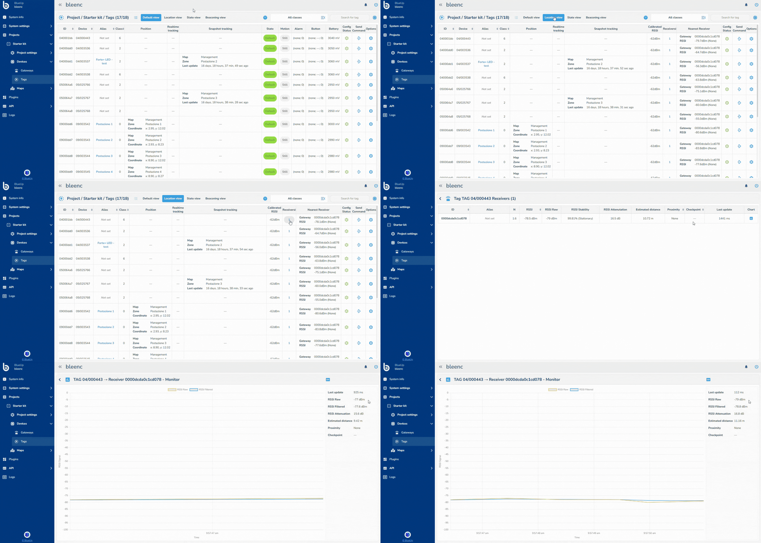
Receiver details
When Receivers is greater than zero, click the count to open the receiver list. The list includes receiver ID and alias, N, RSSI, raw RSSI, RSSI stability, attenuation, estimated distance, proximity, checkpoint information and last update time.
Click View chart for a receiver to inspect its raw and filtered RSSI over time. The chart view also shows the latest signal and proximity values. Use Export data as csv to download its data.
Configuration status
The Config Status icon indicates the tag's configuration update state:
- Grey - No configuration status is available.
- Yellow - The tag is waiting for the new configuration.
- Green - The tag's configuration is up to date.
- Red - The tag is unable to update its configuration.
Commands
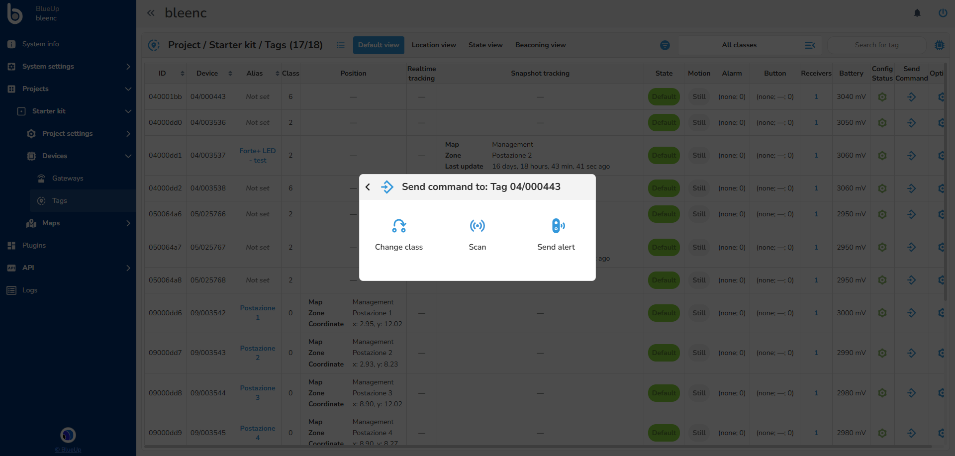
Click Send Command in a tag's row to open the command menu. The commands are:
- Change class - Select a configured destination class other than the tag's current class.
- Scan - Configure and request a beacon scan by entering scanning parameters in the settings form.
- Send alert - Define the alert using the alert settings form, then submit it to the tag.
- Write e-paper - For a tag with a display, enter the values for the frames defined in its class's E-Paper layout configuration.
Tag options
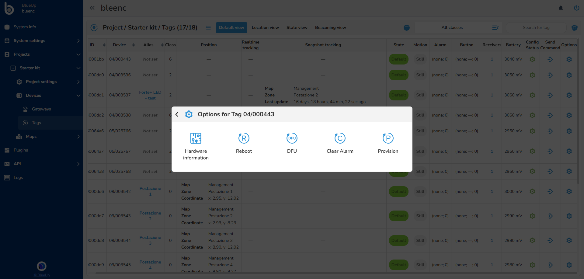
Click Open Tag options in the tag's row. For a detected, non-cached tag, the standard actions include:
- Reboot: restart the tag normally.
- DFU: restart the tag in Device Firmware Update mode.
- Provision: enter a provisioning PIN and restart the tag in provisioning mode.
- Clear Alarm: send a reboot command with the clear-alarm option, when supported by the firmware and offered by the interface.
- Hardware information is available when the system has hardware details for the tag. It displays model, revision, variant, firmware and reported hardware features, including LEDs, buttons, GPIOs, accelerometer, buzzer, vibration and display.
- For cached or non-detected tags, Remove is available instead of the standard restart actions.
Firmware upgrade
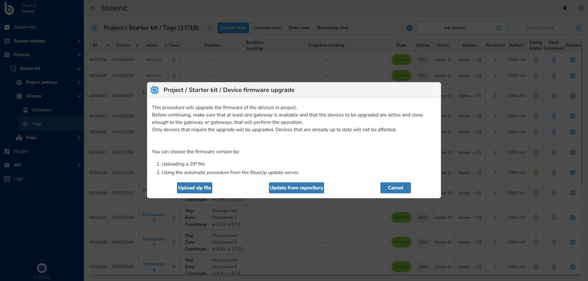
In the right upper corner there is the Firmware Upgrade menu  .
Before starting an upgrade:
- Check that the tags to be updated are detected and report a known firmware version.
- Check that at least one gateway in the project is online and runs firmware 4.2.2.307 or later.
- Place the tags within good radio coverage of the gateways used for the upgrade.
The interface offers two ways to select a firmware package:
- Local ZIP file: select a
.zipfirmware package from your computer. The maximum accepted file size is 16 MiB; larger files are rejected before they are read. - Update from repository: check the BlueUp repository for an available firmware update and download the package if one is available.
When running the firmware upgrade:
- Review the package version and size and the proposed gateways and tags. If necessary, use Advanced settings to restrict the selection. Click Start and confirm.
- Check that at least one gateway displays Package loaded. Status: Valid.
- Monitor the attempts, status, progress and firmware version of each tag.
- Keep the browser session open and connected until the final notification appears.
- Check that every tag you intended to update has a Completed status.
Maps
Maps section is divided into three subsections:
- Configuration: to create and manage maps and zones.
- View: to display the selected map together with the devices and zones.
- Search: to search for a tag and track its position on the map, even if it changes map.
The View and Search subsections become available once at least one map has been configured.
Configuration
The configuration section is used to create, configure and manage the maps in a project.
- Press on Add new map and upload the map image.
- Set the map scale. Select the Set scale tool
 and select two reference points, between which you know the distance. The scale is necessary for the correct position and distance estimation.
Note: horizontal and vertical guides can be added for greater precision.
Once you have entered the distance between the two points, the software will compute the scale of the map. - Add a map description and save.

- Create beacon zones.
Note: for the snapshot tracking (using the beacons) in Zoning mode, the beacons must be associated to a zone. If a beacon is not in a map zone, it will not be used for tag tracking. The Snapshot - Trilateration mode requires only fotr the beacons to be statically positioned on the map
To create a zone, press on the add new zone tool , fill in the ID and zone description and draw the zone: using the left mouse button, press in a spot where one vertex of the zone will be and drag from that point to build a rectangle. If the zone is an irregular polygon, other vertices can be added, by pressing Shift and clicking with the mouse on one of the vertices. Move the vertices to achieve the desired shape and press Enter.
Note: press Esc to exit the zone creation tool.
Horizontal and vertical guides can be added for greater precision.
Press Ctrl to stick a vertex to the guide.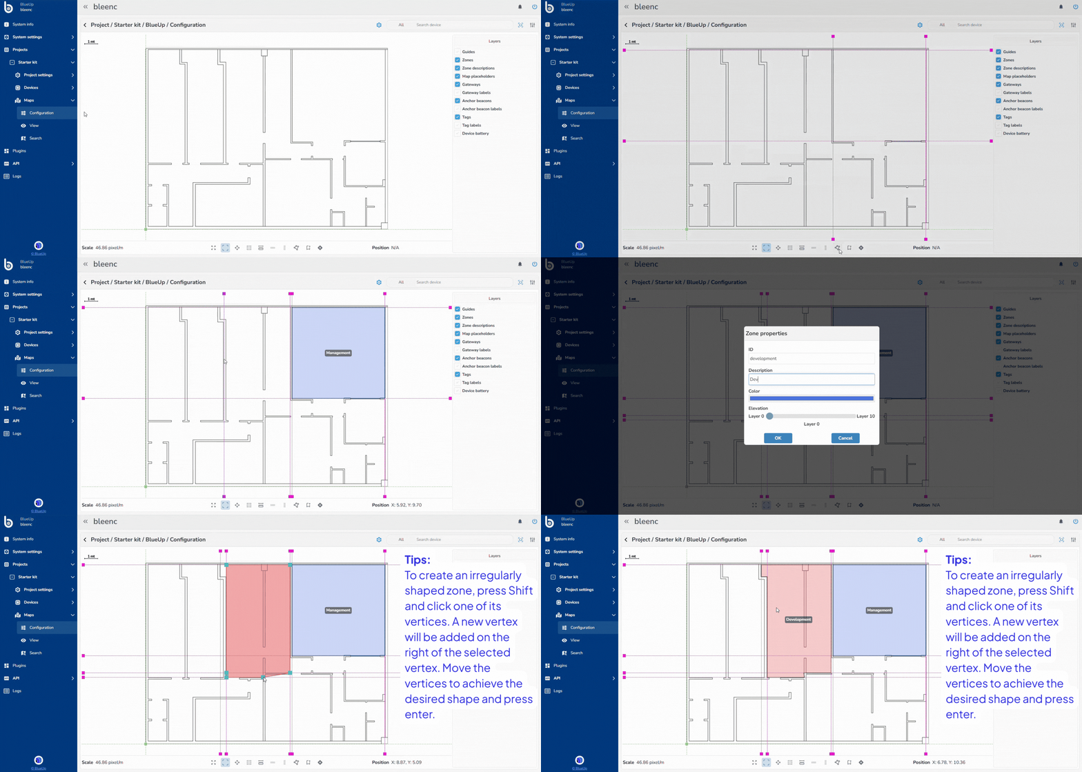
- Place devices on the map. It is possible to place gateways and beacons on the map and, if necessary, also the tags to assign them a fixed position. Press on add new device tool
 , select a device and place it on the map.
Notes: horizontal and vertical guides can be added for greater precision. Press Ctrl to stick a device to the guide.
On the bottom of the page there are some features that can be useful:
- Reset zoom
 to restore the view of the map to the original zoom;
- No tool selected
 ;
- Map move
 to move the view of the map;
- Map area selection
 to zoom the map in a selected area;
- Measure distance
 to measure the distance between two points on the map.
View
The View section allows to display individual tags or tag classes on a map, by selecting the tracking mode to use.
When opening one map, the selection field allows to choose tracking mode and the tags to view:
- Mode: Real-time or Snapshot.
Real-time tracking is used to visualize real-time tags positions.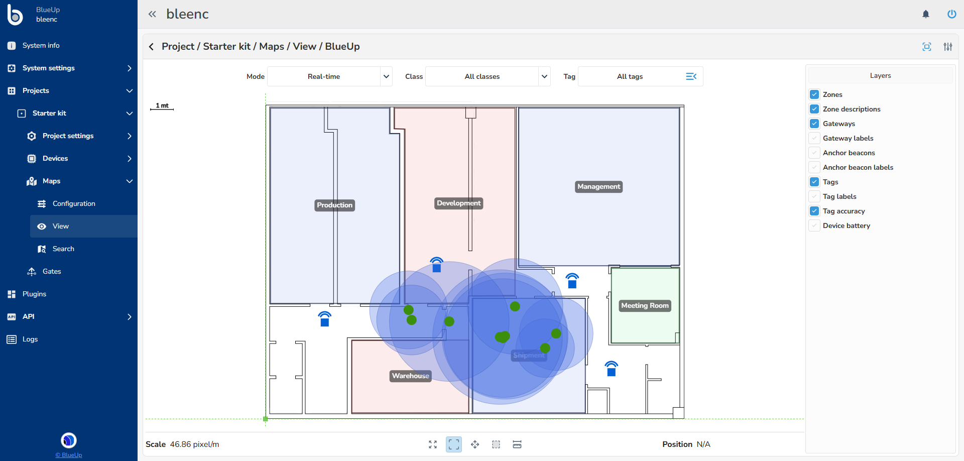 When selecting Snapshot tracking mode and when Zoning is configured, on the map are displayed the number of tags per each zone, divided into moving (outlined circle) and stationary (filled circle) tags.
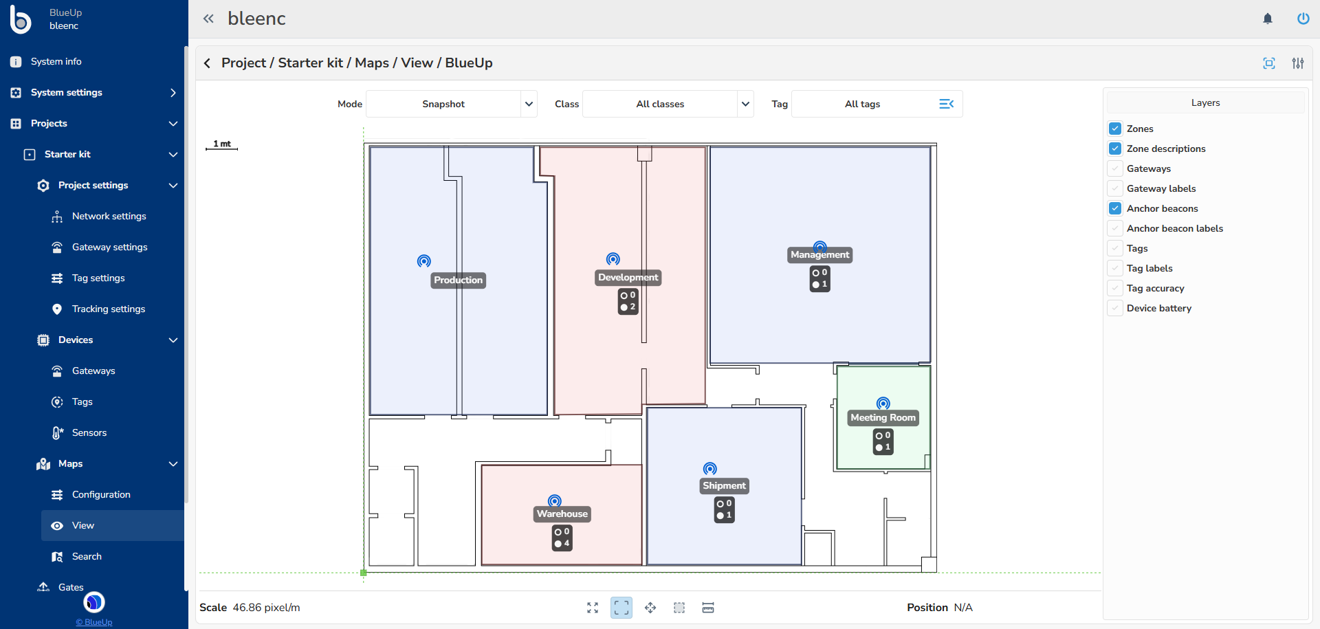 If the scan identifies more than one possible zone, the tag is associated with multiple zones. When a zone includes tags with multiple possible locations, its tag count is displayed as a range: [minimum–maximum].
- Minimum: the number of tags associated exclusively with that zone.
- Maximum: the minimum plus any tags for which that zone is one of the possible locations.
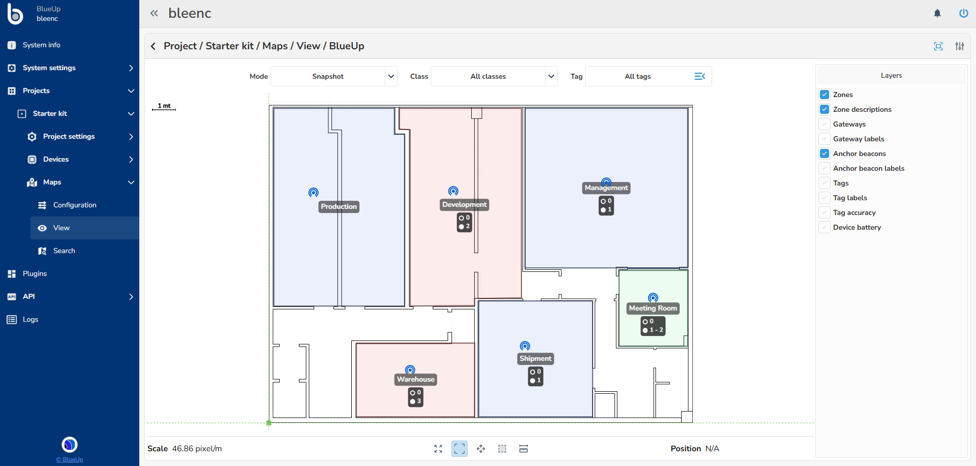
- Class: select the class of tags to view, or leave All classes to visualise all tags on the map.
- Tag: select one tag to view, or leave All tags to visualise all tags on the map.
Search
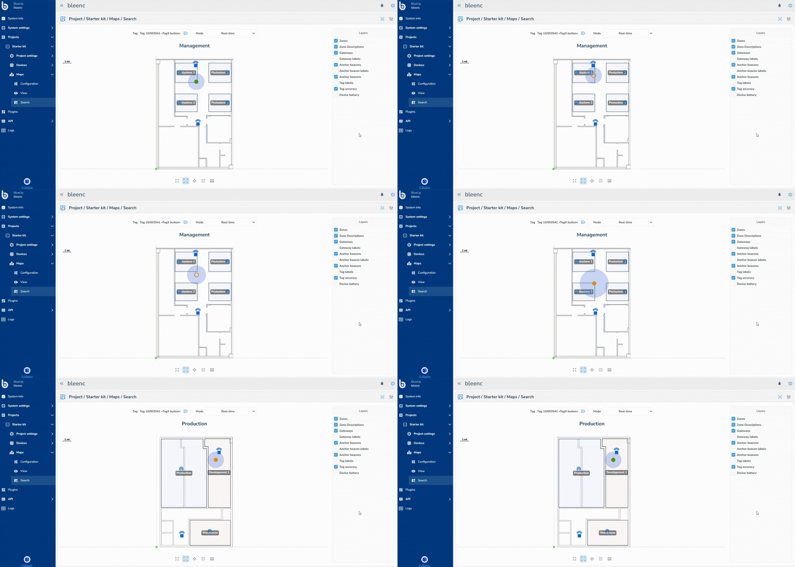
The Search section allows to select a tag and display the map associated with its tracking data.
To search for a tag, after opening the Search section, select a tag from the drop-down menu, and then select the Real-time or Snapshot tracking mode.
When the tag updates its location and changes map, also the visualised map changes.
Real-time mode
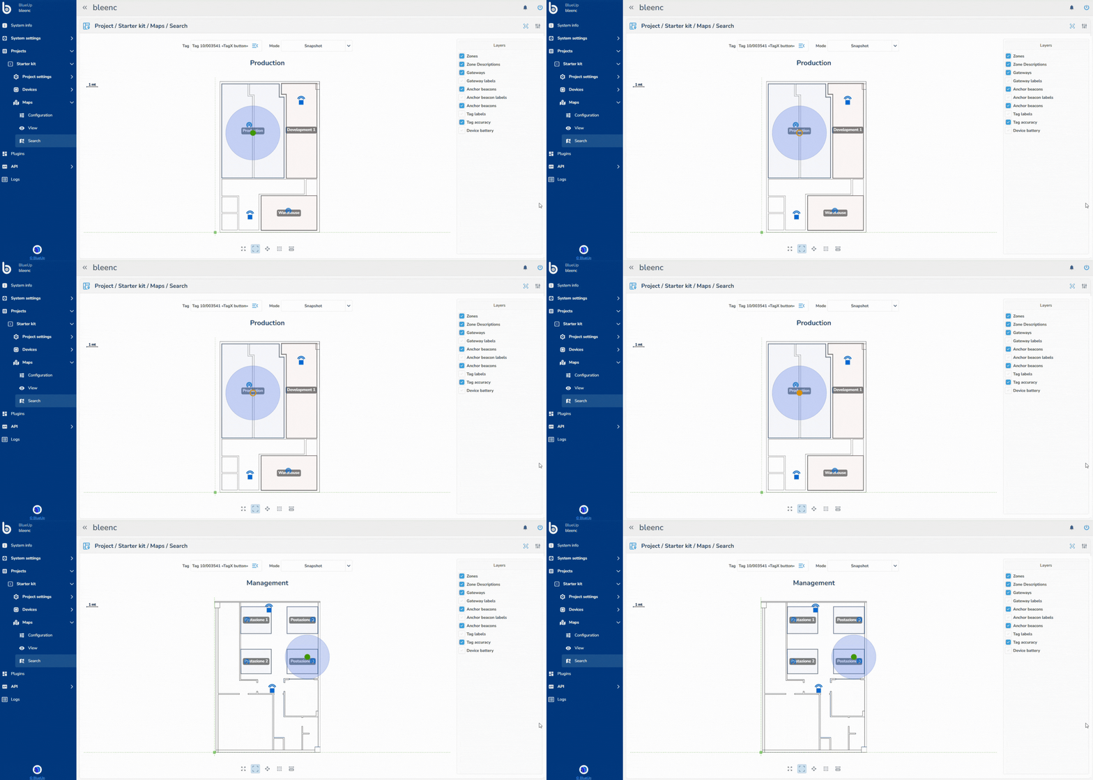
Snapshot mode
If, in Tracking Settings, Snapshot mode is configured as Trilateration, the tag's positions is clculated by triangulating the received beacons after scanning.
Note that the position is updated only after the Anchor beacon scan, as configured in the tag class.
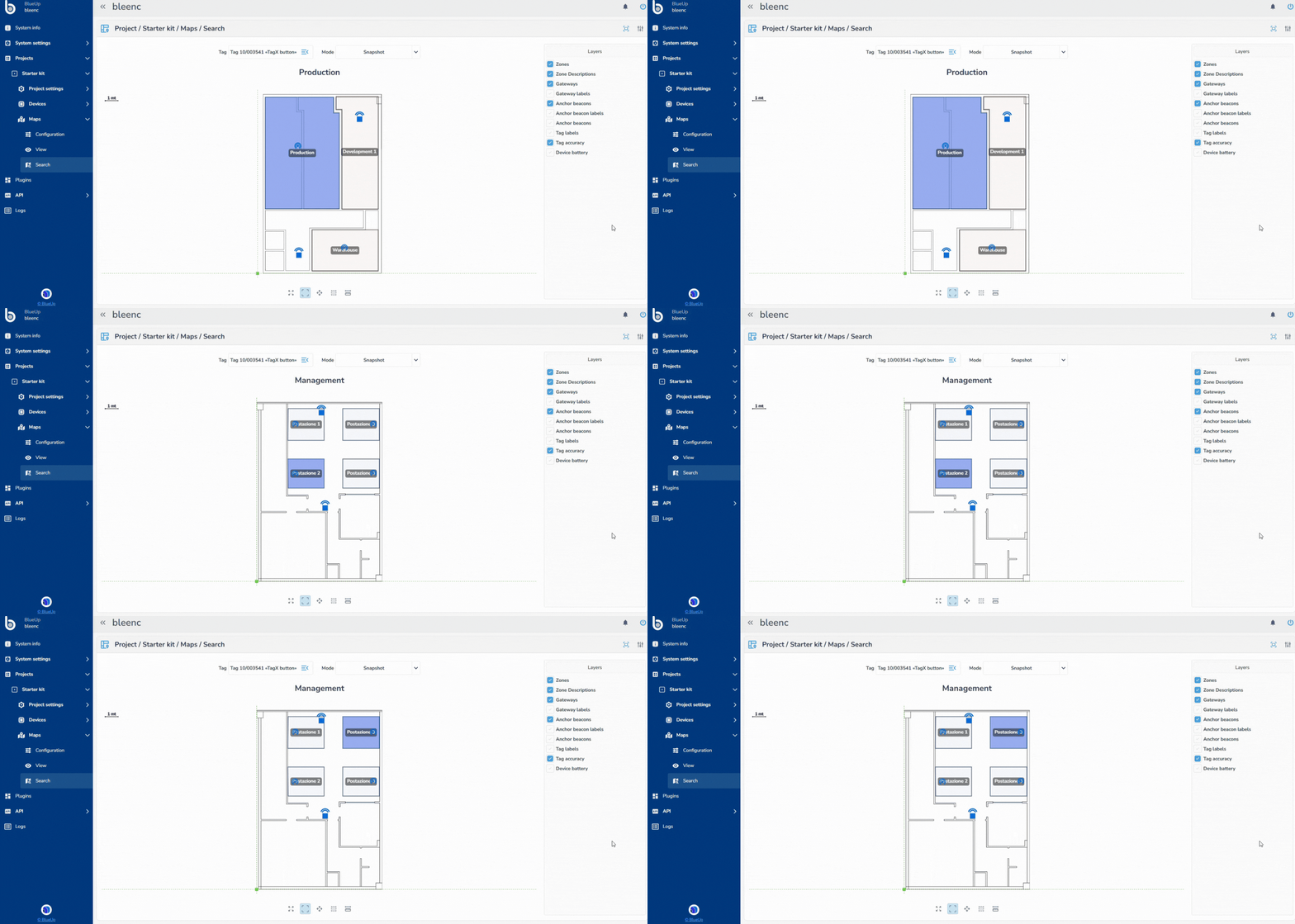
If it is coinfigured as Zoning, on the map is highlighted the zone where the tag is located.
Plugins
Plugins are additional functionalities to the software that are different from the embedded ones. With the plugins the user can extend the native functionalities, without changing the basic structure of bleenc.
To have more information you can reach us by opening a ticket or by writing an email to support@blueupbeacons.com
API
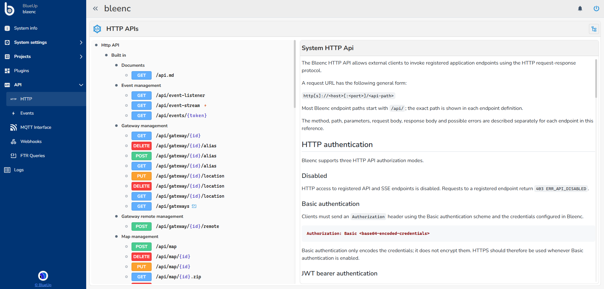
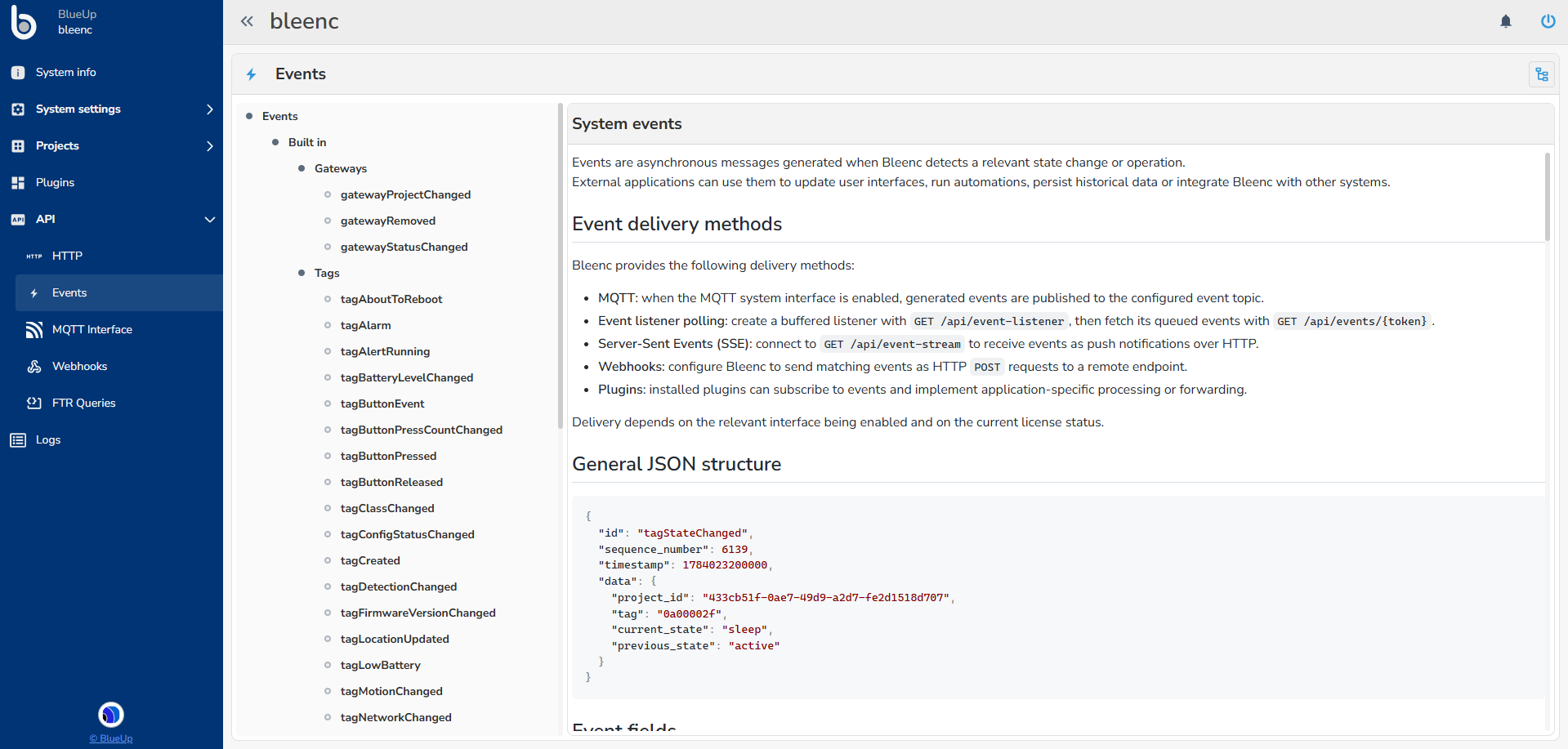
bleenc platform includes dedicated sections for:
- consulting the HTTP API documentation;
- viewing the events generated by the system;
- configuring MQTT Interface topics;
- configuring Webhook connections;
- creating and managing FTR queries.
MQTT Interface
MQTT Interface allows to setup and configure the MQTT Broker interface that manages the requests, responses and events sent by the interface.
In the upper right corner is displayed the selected Broker and its connection status.
The Settings button  allows to enter the MQTT Interface settings in which is possible to:
- remove the broker, to select a different one;
- refresh the broker connection.
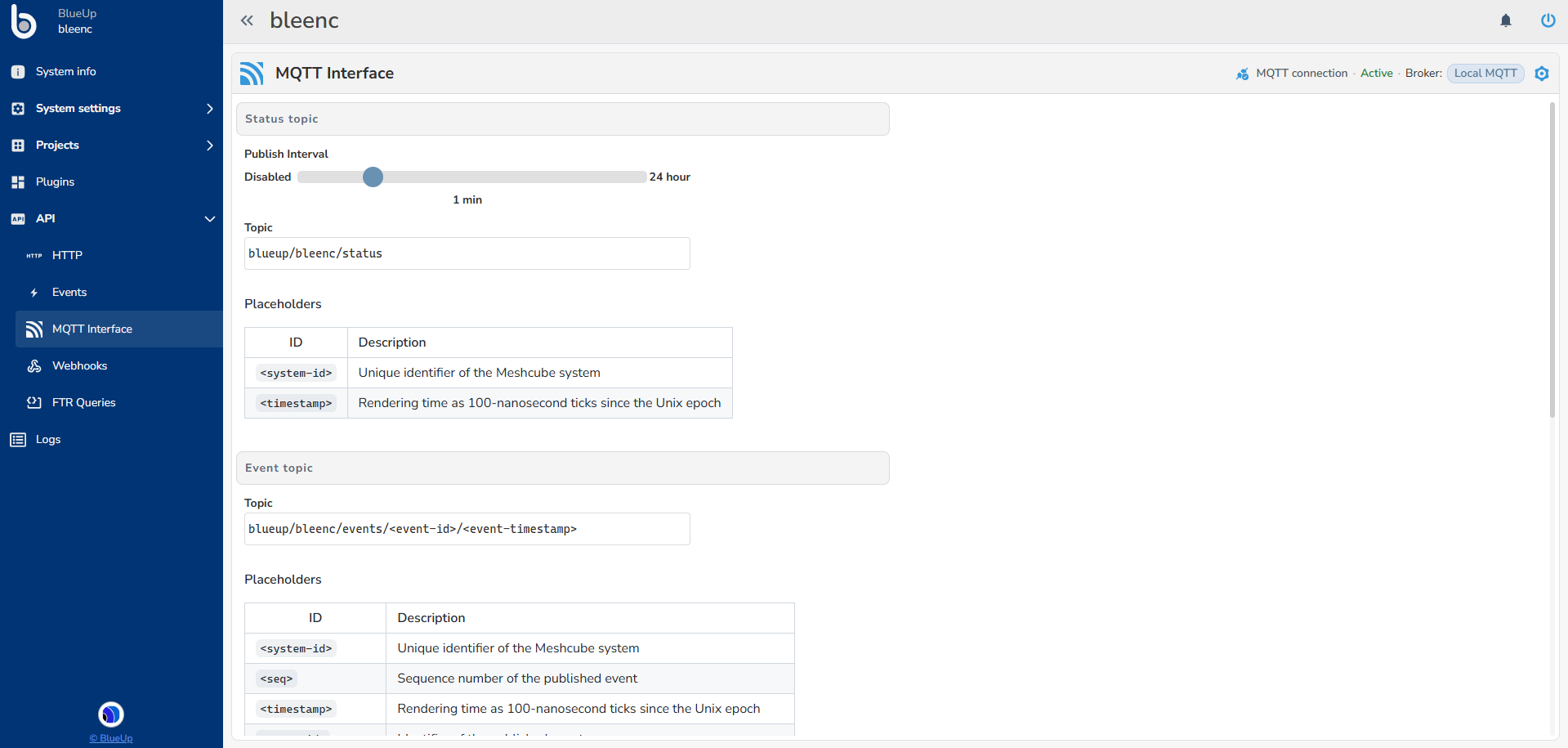
Below it is possible to configure the different topics that can be received/sent through MQTT.
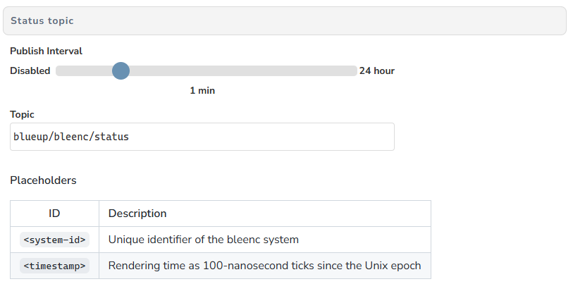
Status Topic
This topic contains the system status information. This kind of topic has a configurable sending frequency, from disabled to every 24 hours.
In the topic field can be specified the Status Topic structure. The default structure is blueup/bleenc/status, but it is possible to add other parameters, called Placeholders, that will be displayed in the topic:
- system-id is the system unique ID;
- timestamp is the system UNIX timestamp.
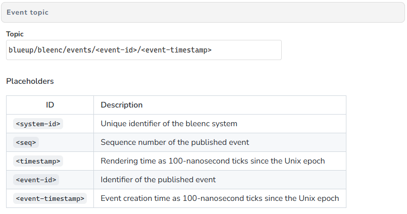
Event Topic
This topic contains the events sent by the system. The default structure is blueup/bleenc/events/<event-id>/<event-timestamp>.
Other Placeholders that can be defined are:
- system-id is the system unique ID;
- seq is the event sequence number
- timestamp is the system UNIX timestamp;
- event-id is the event identifier;
- event-timestamp is the timestamp of the event, in hundredths of nanoseconds format.
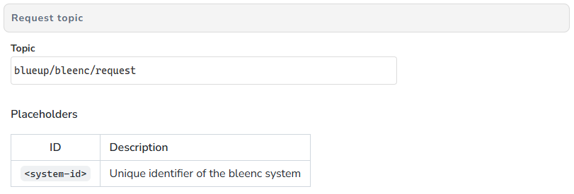
Request topic
This topic is used by the client to send the requests to the system. The default structure is blueup/bleenc/request/#.
This structure can contain Wildcards, that are:
+is equal to any word in that given position;#is equal to anything in that given position, that can be a word, an identifier, a structure.
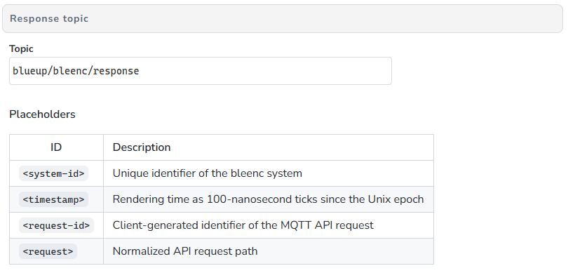
Response topic
This topic contains the responses to the requests. The default structure is blueup/bleenc/response.
The possible Placeholders are:
- system-id is the system unique ID,
- timestamp is the system UNIX timestamp,
- request-id is the request identifier generated by the client in the request topic,
- request-name is the request name.
Webhooks
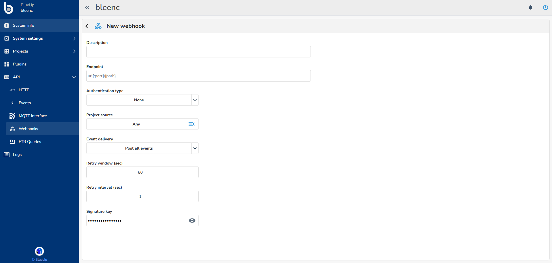
The Webhooks section displays all configured webhooks in a table and allows users to create new ones.
To configure a webhook, specify the following parameters:
- Description - a short description used to identify the webhook.
- Endpoint - the destination URL to which events will be sent. A port and path may also be specified, if required.
- Authentication type - the authentication method used to connect to the endpoint. Available options are None, Basic, and Bearer.
- Project source - the project from which events will be collected. You can select a specific project or Any to collect events from all projects configured in the system.
- Event delivery - defines which events will be sent to the endpoint. The available options are:
- Post all events;
- Post only selected events;
- Post all except selected events.
- Retry window - the period, in seconds, during which the system will attempt to resend an event if delivery fails.
- Retry interval - the interval, in seconds, between consecutive delivery attempts.
- Signature key - the key used to generate the signature associated with webhook requests, allowing the receiving system to verify their authenticity.
FTR Queries
FTR Queries are scripts that allow to define some functions for the call of some APIs.
FTR stands for Filter, Transform, Reduce and these functions are to be written in JavaScript.
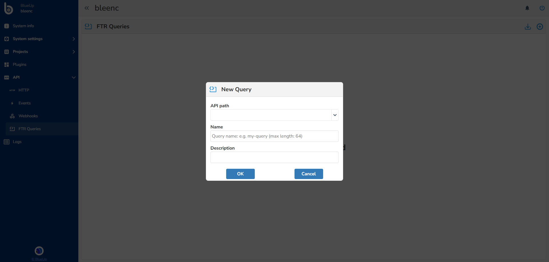
When adding a new query (by pressing ) the user has to define:
- the API path, that is the API call to which the FTR will be applied. The currently supported API calls are:
/api/gateways/api/tags/api/tag/{id}/receivers/api/webhooks
- the name of the query without blank spaces;
- query description;
The script can contain Filter, Transform and Reduce functions, described in the following.
All the three functions are optional
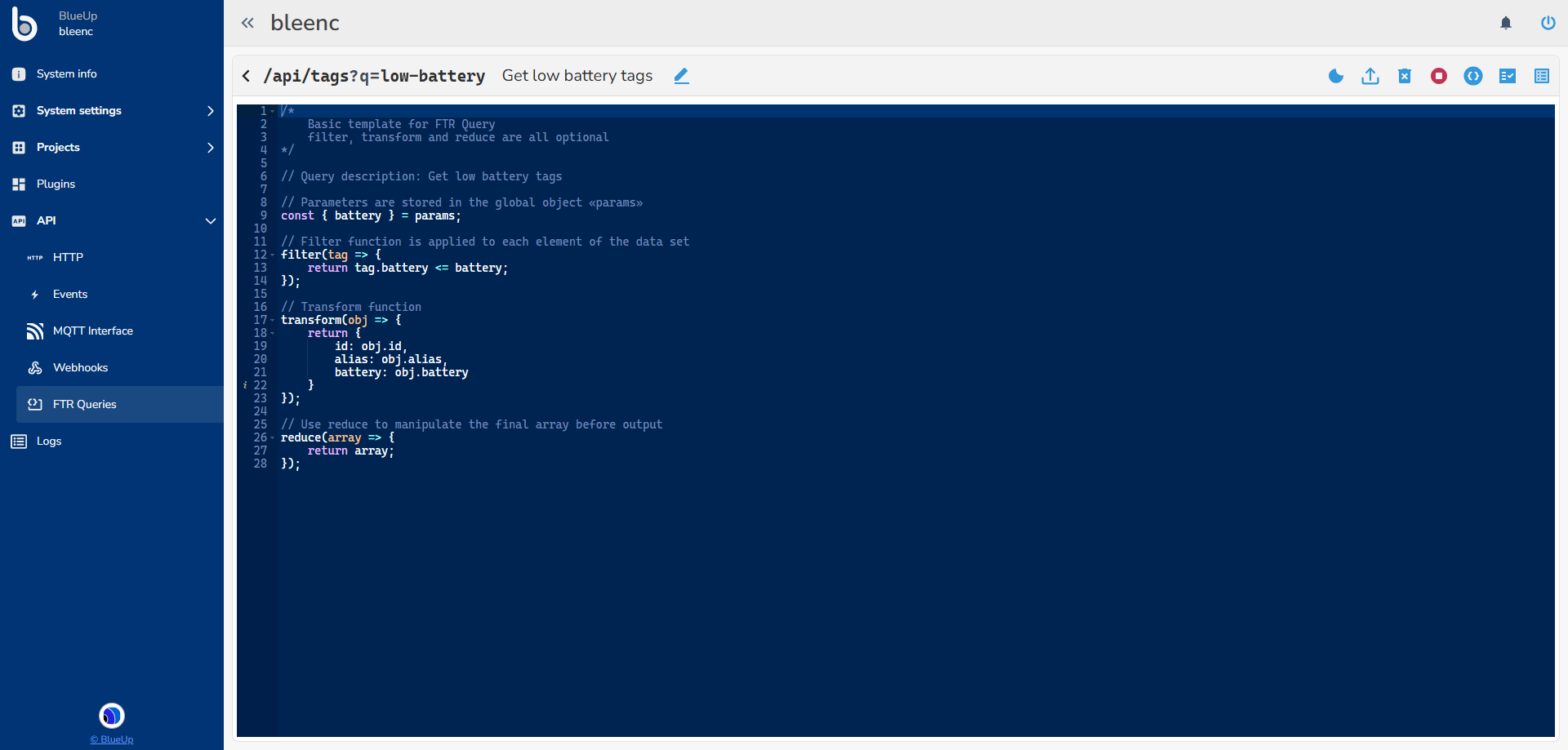
When creating a new query, a query template will open.
Above the code field, there are some useful buttons:
- to save the code changes;
- to edit the Api, name and description of the query;
- to export the query;
- to delete the query;
- to enable / disable the query. When the query is disabled, calling the API with query will return the same response as calling the API without query;
 to automatically format the code;
 to check the validity of the code;
 to show / hide the list of defined parameters. When showing, it is possible also to define a new parameter.
Filter
When defining the Filter function, it is applied to each element of the data set. When defining the filtering rule, the data set will be reduced to the only elements that satisfy the filtering condition.
Consider, for example, the /api/tags call that returns the array of all the tags in the system. The user may want to retrieve only the tags having battery lower than a defined battery level. This is possible by defining the filter function.
Example in which are returned only the tags which battery is at o below a set value:
filter(tag => {
    return tag.battery <= battery;
});
Transform
The Transform function is used to retrieve only the desired fields of the data set.
Taking as example the /api/tags call, it is possible to take only the fields the user is interested in.
Example in which are retrieved only id, alias and battery of the tags:
transform(obj => {
    return {
        id: obj.id,
        alias: obj.alias,
        battery: obj.battery
    }
});
Reduce
The reduce function is used to manipulate the output array.
A possible usage is to return as array the tags that satisfy the query:
reduce(array => {
    return array;
});
After setting up the FTR Query, save it and enable the query, by pressing button.
To call the defined API with the defined query, the API call structure is (example for /api/tags):
<host>/api/tags?q=<query-name>
Logs
System logs
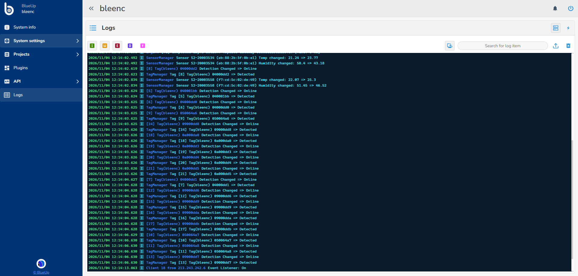
The Logs keep track of the system messages that can be used to track the software activities. The logs can be accessed by pressing  button in the upper right corner.
It is possible to filter the logs that are displayed by enabling or disabling different log levels, in the upper left side of the page, by choosing among:
- Information
- Warnings
- Errors
- Debug - used for debugging purposes. It is suggested to keep them disabled when not needed.
- Verbose - used for diagnostic purposes. It is suggested to keep them disabled when not needed.
System events
The system Events page can be accessed by pressing  button in the upper right corner.
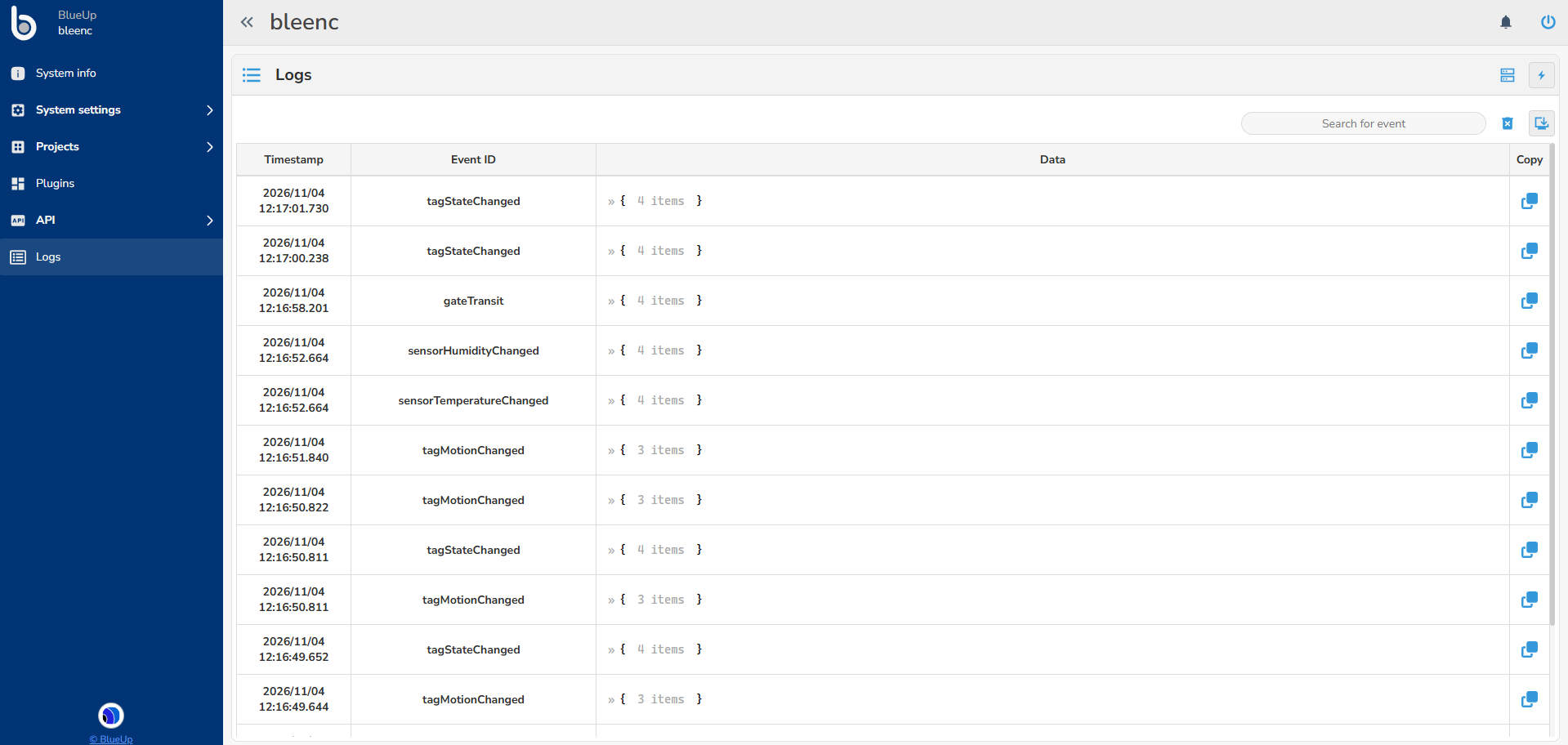
These logs contain all the events of the system, if the event tracking is enabled by pressing the  button.
The full description of the events can be checked in API Events tab.