MeshCube User Guide v.6.x
MeshCube is an IoT platform for positioning, tracking and distributed monitoring developed by BlueUp.
MeshCube uses Wirepas Mesh 2.4GHz network technology as backbone for device communication.
MeshCube is provided with a user-friendly web interface that can be used for monitoring and configuration of Mesh devices.
Specifications
Here are summarized the recommended system specification for different project sizes.
These are recommended specifications for typical projects. Contact us if you have doubts.
| Project size | CPU | RAM | HardDisk space |
|---|---|---|---|
| Small 20 Anchors + 20 Tags |
4 cores | 4GB | 128 GB |
| Medium 100 Anchors + 200 Tags |
4/8 cores | 8GB | 128 GB |
| Large 500 Anchors + 1000 Tags |
8+ cores | 16GB | 256 GB |
The system should be installed on a Debian - based Linux system.
Ubuntu 22.04 or later is recommended.
MeshCube web interface, described here, is divided into sections for a more user friendly navigation.
In the upper right corner of the web interface there is the notification center  where are shown the useful notifications from the system to the user and also where are shown the background processes running in the system.
By pressing the  button in the upper-right corner, the system opens a pop-up menu from which it is possible to logout the system, restart the service or restart the server.

System Info
This first tab of the BPE Web Interface displays all the necessary information about the software, the license and network.
From this interface the user can check if there are new software updates available and to update the software by pressing  button.

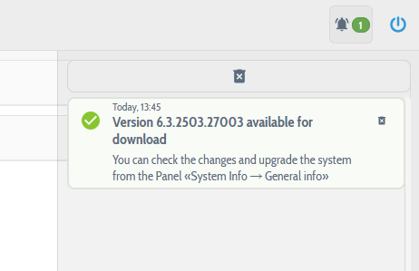
Starting from MeshCube v. 6.3.2503.27, in in the software settings the check upgrades is enabled, when there is a new system upgrade availabe the user receves a notification about it. The notification, unless deleted, remains for 24 hours.
The software upgrade is not automatic and has to be performed by the user.
When pressing on the ![]() button, it is possible to retrieve the changelog of all the MeshCube versions to track the changes.
button, it is possible to retrieve the changelog of all the MeshCube versions to track the changes.
The cangelogs are available also on the dedicated changelogs section.
License
MeshCube is a licensed software.
The license is applied to the server on which the service is running.
In the System info is summarized information about the license of your MeshCube:
- Status signals if the license is valid or not;
- Expires on is the expiry date and time of the license. After the license has expired, the service will be still available for 2 hours. After the 2 hours, the service will stop responding to the users requests;
- Maintenance expiry is the date and time when the maintenance to the MeshCube will end. For maintenance is intended the possibility to update the software with the new releases. If the license is still valid, but the maintenance is expired the software can not be updated;
- Capabilities are the proprieties of the software the user has access to. The user can have a limited license version, without support of some capabilities. The possible capabilities are:
- Whitelabel is a new capability introduced in MeshCube that allows to rebrand and customize the MeshCube web interface with custom name, company and others. Contact us for more information;+
- Maps is the maximum number of maps that the user can create in MeshCube;
- Anchors is the maximum number of Anchors that are supported. If the number of anchors exceeds the maximum allowable the license will become Not valid;
- Tags is the maximum number of Tags that are supported. If the number of tags in the system exceeds the maximum allowable the license will become Not valid;
- Mesh Networks can be "All allowed" or can be a list of allowed networks. This sets the quantity and the network addresses that can be managed by MeshCube instance;
- MeshIPS module if enabled, MeshCube can manage the positioning function;
- MeshSense module if enabled, MeshCube can manage the sensor nodes;
- MeshBeacon module if enabled, MeshCube can manage the beaconing of the nodes;
- Automation module if enabled, MeshCube can manage the Automation module. Contact us for more information.
Note: When the license is about to expire, starting from 1 month before the expiry date, the system sends a daily notification to the user to remind to renew the license.

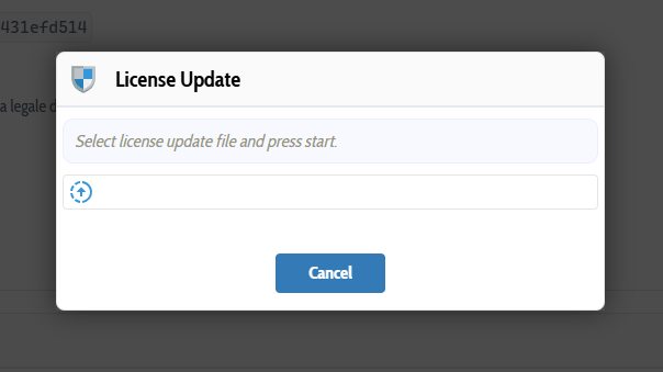
If your license is expired and you have received the new license file, it has to be uploaded by pressing the icon in the License section.
Select and upload the license file you have received to renew the license.
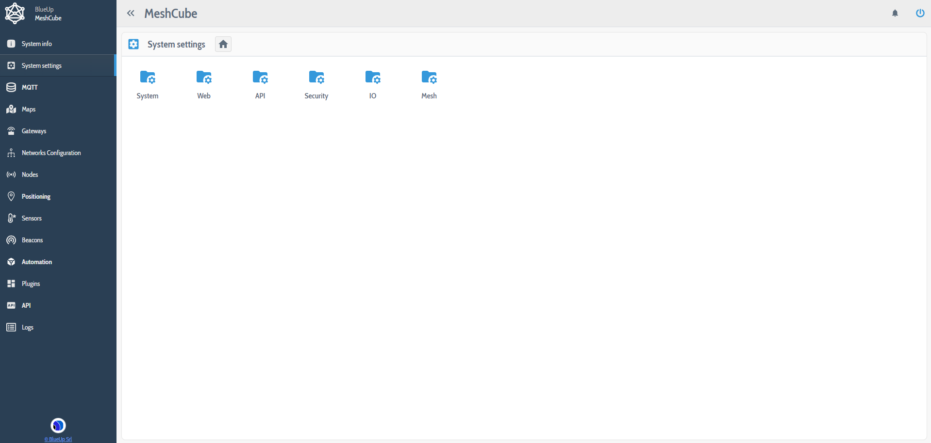
System Settings
This section gathers all the possible settings of the system: it is divided in subsections where settings and configurations are collected based on their functionality.
System - Timezone
This setting allows to setup the timezone where the server is located. The timezone is useful for Maintenance and other basic operations that are time-related.

System - Maintenance
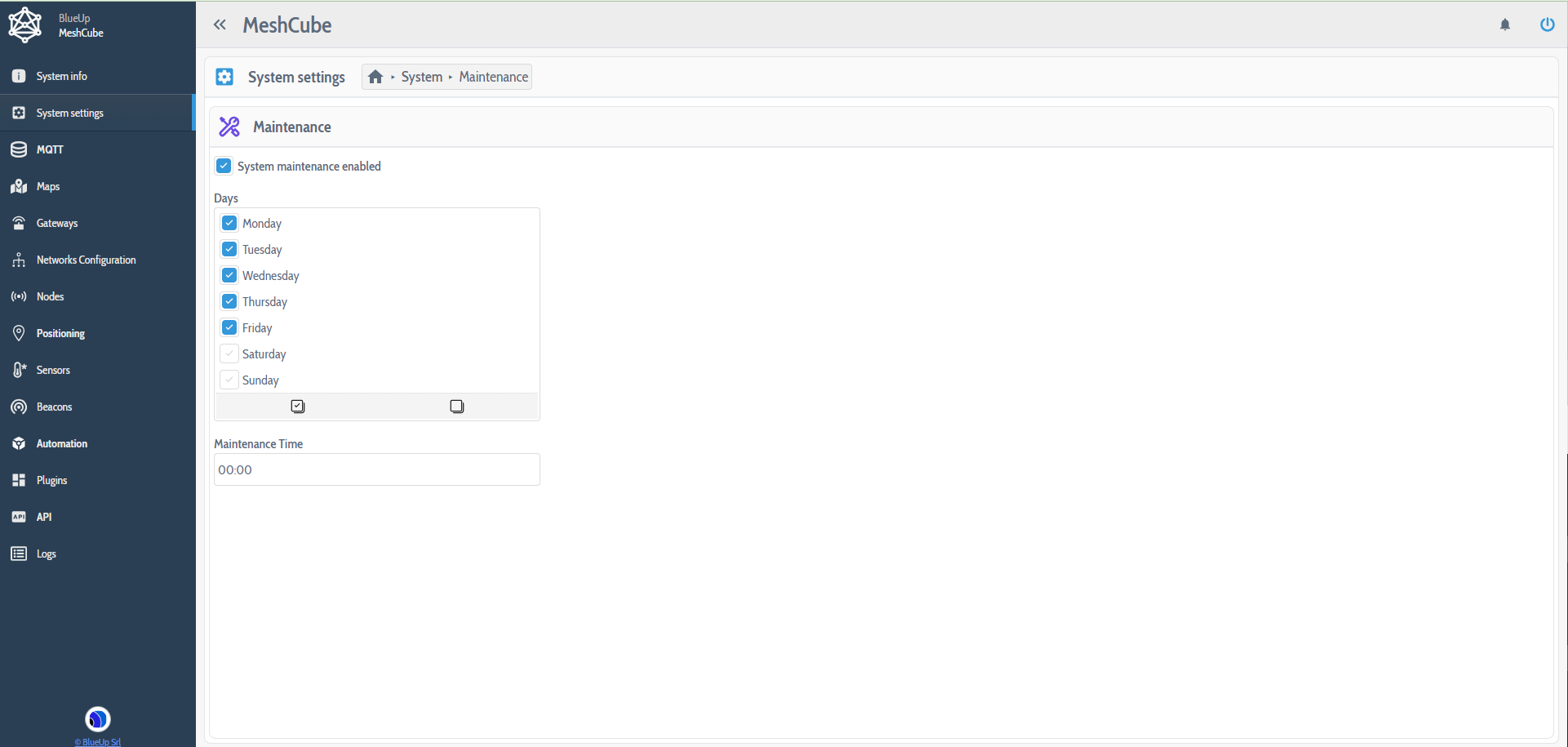
This section allows to configure the Maintenance of the system. During maintenance the system performs some operations of checking, optimizing, updating and deleting expired data from the system. During these operations the system can pause some basic functionalities of MeshCube.
- System maintenance enabled flag allows to enable or disable system maintenance. It is suggested to keep system maintenance enabled;
- Days - table that allows to select the days when the maintenance will be performed;
- Maintenance Time is the time (in 24h format) when the maintenance is performed.
Since during maintenance some basic functionalities can be paused, when configuring maintenance period it is suggested to set days and time when the system is not used, to not to interfere with system functioning.
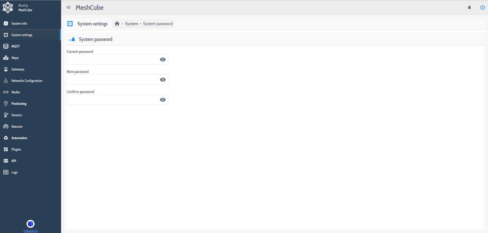
System - System Password
This setting allows to change the access password of the MeshCube interface.
After inserting the current password and the new one, the  button will appear to save the new password.
If the New password and the Confirm password do not coincide the button will not appear.
If the inserted Current password is not correct an Error pop-up will appear.
System - Email Service
This section can be used to setup an email service. This service can be used for testing purposes or to configure Plug-ins that support email services.
- SMTP Server to be selected among the SMTP servers setup in IO - SMTP Servers;
- Sender name to be able to recognize the email coming from MeshCube service;
- Sender email address is the email address from which MeshCube will send an email.

System - Software settings
This setting allows to decide which software release the user wants to use, among:
- Stable is the officially released version of the software;
- Beta is a Beta version of the software, before stable release;
- Dev is a Development version of the software;
- Custom available only if a custom version of the software has been required. In this case BlueUp will provide the user also with Repository, App id, App key to insert in the settings to download the updates related to the custom version.
By selecting one of the software releases, when updating the software, it will be updated to the latest available version of the chosen release.
Note: if you choose Beta or Dev versions, consider that they are not stable versions, therefore there can be some bugs in the system. If you find any, please report the bug or problem by opening a ticket or by writing an email at support@blueupbeacons.com
The Check upgrades checkbox allows to enable the automatic check of the new available software upgrades. If a new version is found, a notification will appear in the notify center.

Web - WebServer
The WebServer settings allow to setup the HTTP interface settings.
- Server URL is used to setup the URL at which the server is reachable;
- Certificate allows to select (in case of HTTP S connection) the certificate corresponding to the HTTPS connection. The certificate is setup in Certificates settings;
- Listening port is the port at which the service is listening;
- Workers is the number of processes that the system can open at the same time;
- Check idle connections is a function that scans for active connections to the server and automatically closes the connections that have been idle for at least 1 hour;
- Use reverse proxy is an advanced setting related to the proxy. Leave to default value if not sure about its use;
- CORS enabled allows to setup the cross calls to the system from other domains. For more information refer to Cross-origin Resource Sharing.

Web - mDNS
mDNS is a protocol that allows to discover network services and devices in the local network with their hostnames instead of IP addresses. This procedure can be applied only if the MeshCube server is installed on premises and not in cloud.
Make sure that mDNS is configured in your network interface.
- Service Description is the description of the service that allows to easily discover the service in the network;
- Service hostname is the hostname at which the service is reachable, instead of the IP address.
When defining the service hostname, the MeshCube server will be available also at <service_hostname>.local address in your browser.

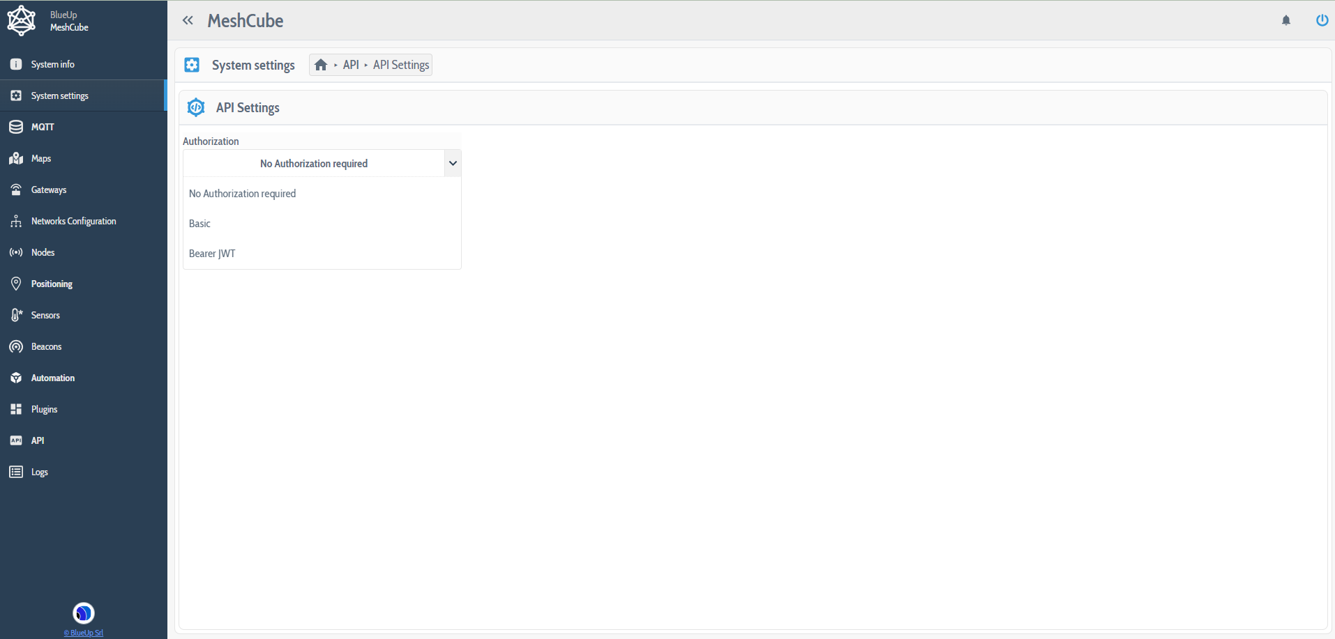
API - API Settings
This setting allows to setup the security level for what concerns the HTTP API calls.
- No authorization required - the APIs can be called without any specific authorization;
- Basic - the user has to specify a Username and Password to use when calling the API;
- Bearer JWT - the most secure authorization mode, described here. To use this modality, the user has to generate a JWT Token in JWT Tokens section.
API - JWT Tokens
To authenticate using Bearer JWT method, a JWT Token has to be generated to be used when calling an API. To create a new Token press on  and fill in the following fields:
- Description of the JWT token;
- Expires to decide if the token expires or not. In case this field is checked, the user has to set an expiry date and time;
- IP addresses is the list of IP addresses that can call the APIs. If left blank, all IP addresses will be allowed;
- Access Rule options are:
- Allow all to allow the access to all API calls;
- Allow selected APIs to allow to call only the selected API calls;
- Deny selected APIs to deny to call selected APIs;
- Allow all to allow the access to all API calls;
- Max invocation per hour is the maximum number of API calls that can be invoked per hour with this JWT token.

Once that a Token is saved, it will appear in the list of JWT Tokens.
In the table, for each generated JWT Token are summarized the configured parameters.
Moreover, for each token it is possible to:
- Edit the token

- Download the token

- Enable
 or Disable
  the token
 - Delete the token


Security - Certificates
This section allows to upload and store all the certificates that are used for HTTPS and/or MQTTS connections.
To upload a certificate, press on the upload button  . The acceptable certificate format is PKCS#12.

IO - MQTT Brokers
In this section is possible to setup the MQTT Broker for data transmission. For each MQTT Broker are defined the parameters of the connection to the Broker.
A broker configuration can be imported or created from scratch. Also an existing configuration can be cloned and changed, instead of creating a new one.
In case the same configuration is intended to be used with multiple broker connections, the Username field should be set to auto when configuring.

IO - SMTP Servers
This setting is used to setup SMTP server for the emailing function. When configuring a new SMTP server the fields to fill in are:
- Host
- Port
- SMTP connect options are:
- Auto
- SSL
- TLS
- Auto
- Username
- Password

Mesh - Mesh handler
This setting allows to setup the Mesh packet storage in a database:
- Enable / disable data storage;
- Packet storage retention days is for how long packets are stored in MeshCube database.

Mesh - Gateways Settings
This flag allows to decide whether to periodically scan the local network, searching for new gateways to connect.
The Check firmware upgrade on maintenance (starting from MeshCube v6.2) allows to enable the firmware upgrade check for the TinyGateways during the maintenance period. Additionaly, the user can also decide whether to automatically upgrade the firmware when the new firmware version is available.

Mesh - Nodes - Alert Templates
In this section are collected all the alert templates that have been created or it is possible to compose a new alert template to send to the nodes. Alert templates are useful for node alerting, without having to compose the alert manually every time.
In the alert template the user has to specify:
- the ID of the alert to easily recognize it;
- the description of the alert;
- buzzer (if enabled) period, number of repeats and duty cycle in percentage;
- vibration (if enabled) period, number of repeats and duty cycle in percentage;
- LED (if enabled) period, number of repeats, duty cycle in percentage and the color mask.
The alert then can be sent to the nodes in the Nodes section.

Mesh - Tags - Tag positioning settings
Tag Positioning settings allow to define the rules for Tag positioning. The settings are divided into 3 configuration levels:
- Basic
- Extended
- Advanced
each described in the following.
Note: When choosing e.g., Basic settings, the parameters in Extended and Advanced settings will be configured with default values.
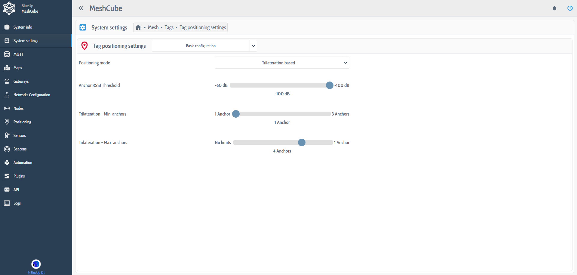
Basic positioning settings
- Positioning Mode:
- Trilateration based: the exact position of the Tag is calculated geometrically, based on the signal strength indicator RSSI of all the anchors that are near the tag (refer to the algorithm);
- Zone based: when defining the zones on the map, the Anchors that are in a zone are automatically associated to that zone. In this case, the algorithm estimates the best zone where the tag is, based on the RSSI value. After that, the algorithm estimates the position of the tag inside that zone (refer to the algorithm);
- Trilateration based: the exact position of the Tag is calculated geometrically, based on the signal strength indicator RSSI of all the anchors that are near the tag (refer to the algorithm);
- Anchor RSSI Threshold is the minimum RSSI value that can be used when evaluating the position of the tag. If RSSI between the tag and an anchor is lower than the set value, the anchor is not considered when evaluating the tag position;
- Min. / Max. Anchors is the minimum and maximum number of anchors to consider when evaluating the position of the tag.
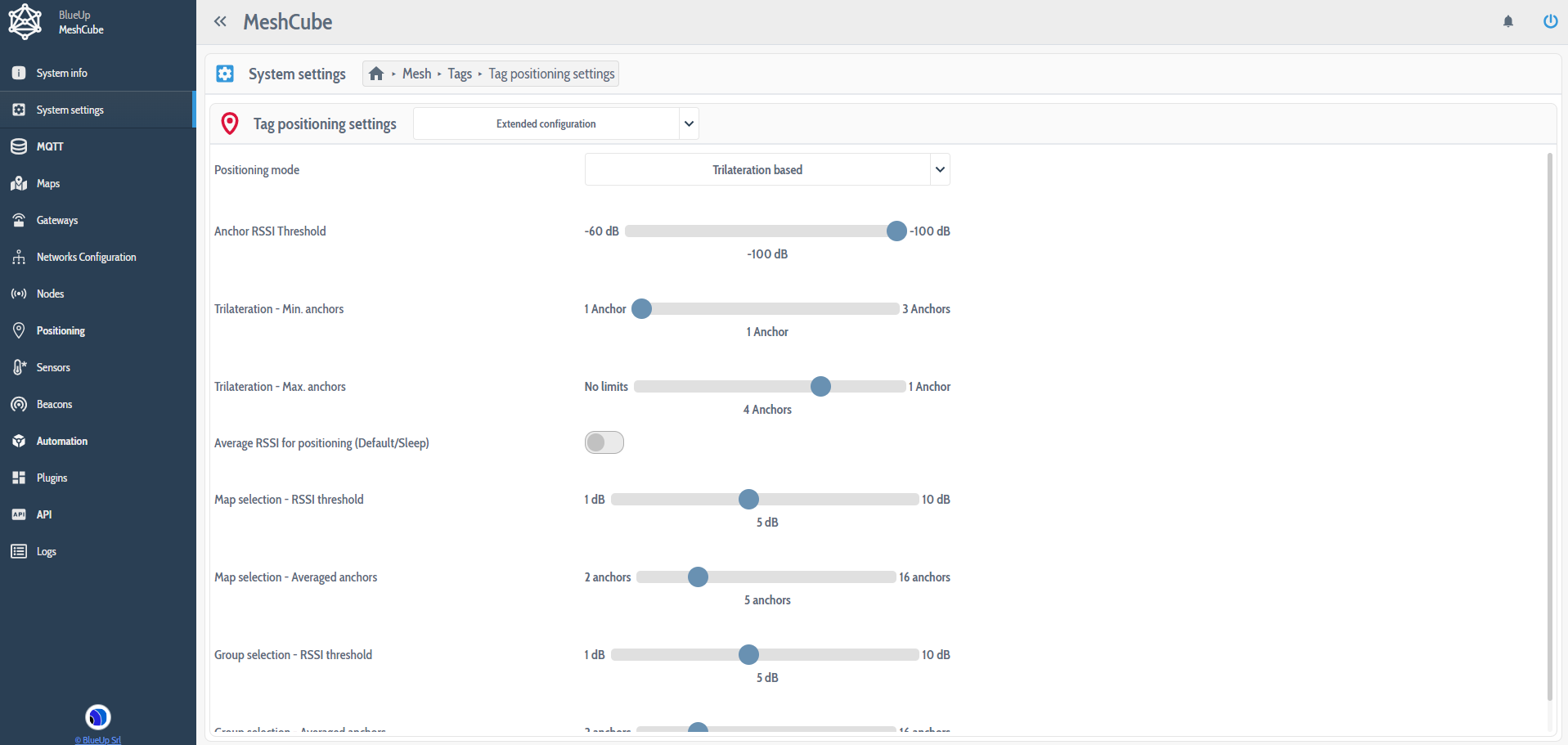
Extended positioning settings
Additionally to the Basic configuration:
- Average RSSI for positioning (Default/Sleep) a switch that allows to decide whether to take into account positioning changes when the tag is in Default or in Sleep mode;
- Map / Group selection - RSSI threshold is the min RSSI value to decide that one Map or Group is better than the other(s), comparing the Max RSSI value of the Map or Group;
- Map / Group selection - Averaged anchors is the number of anchors to consider when calculating the average RSSI. The average RSSI is taken into account when the RSSI difference between Anchors of the Map or Group is lower than the RSSI Threshold value.
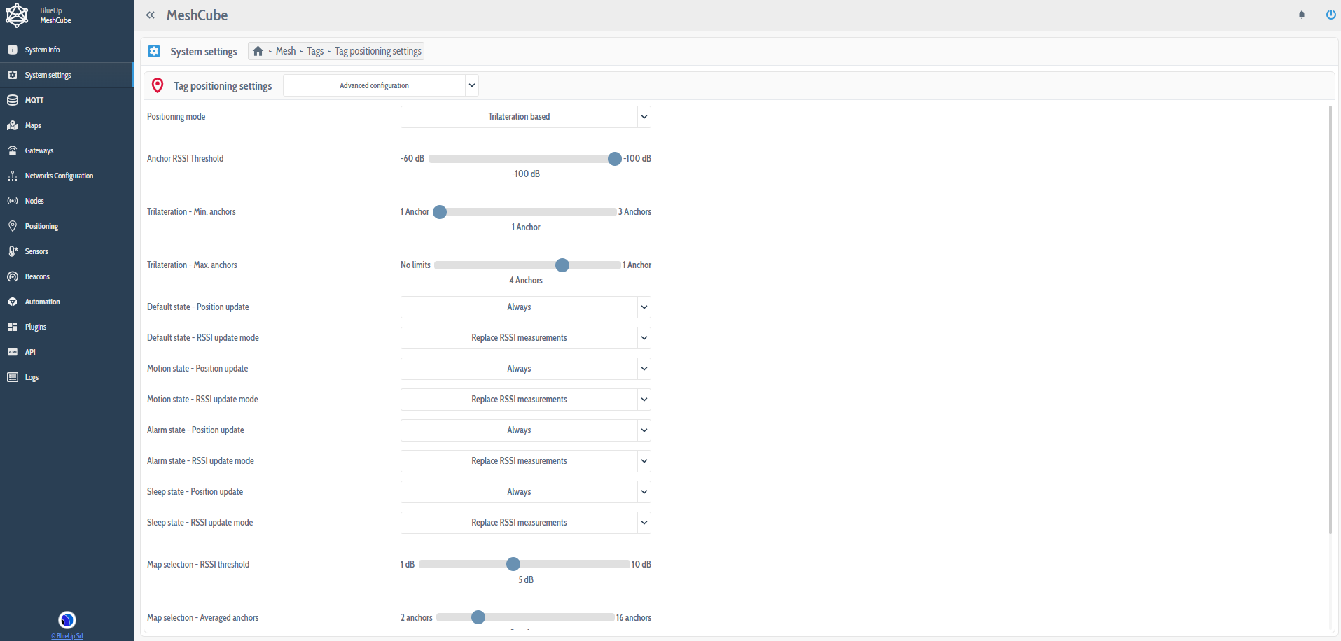
Advanced positioning settings
Additionally to the Extended configuration, the Advanced configuration allows to define the positioning update rules for each state separately. For each state it is possible to set:
- Position update selecting between Disabled, State transition and Always:
- State Transition means that the position of the tag will be updated only when the tag changes its state;
- RSSI update mode between Replace RSSI measurements and Average RSSI measurements, with respect to the previous ones.
Trilateration algorithm
In case Trilateration is chosen as positioning mode the algorithm performs the following positioning steps:
- If in the system there are multiple maps, the algorithm first selects the best Map where the tag is.
- If on the map are defined the different Zones, the algorithm selects the Zone where the tag is, based on the highest RSSI between the tag and the anchors of the zones.
- Finally, the algorithm evaluates the position of the Tag, based on the RSSI level between the tag and the anchors, applying the Trilateration algorithm.
Zone algorithm
In case Zone is chosen as positioning mode the algorithm performs the following positioning steps:
- If in the system there are multiple maps, the algorithm first selects the best Map where the tag is.
- If on the map are defined the different Zones, the algorithm selects the Zone where the tag is, based on the highest RSSI between the tag and the anchors of the zones.
- Finally, the algorithm evaluates the position of the Tag inside the Zone, based on the RSSI level between the tag and the anchors, applying the Trilateration algorithm.
Note: in case the algorithm is not able to define univocally one zone in which the tag is (e.g. RSSI difference between two zones is lower than the Group RSSI threshold) the position of the tag will be in an array of zones and the trilateration algorithm will be applied considering all the anchors of the array of the zones.
Mesh - Sensors - Mesh Sensors
This setting allows to setup the desired Temperature measurement unit, choosing between Celsius and Fahrenheit. Data will be displayed with the set measurement unit in Sensors section.
It is also possible to setup the Data retention days, that is for how long data is stored in the MeshCube database.

MQTT
MQTT is a publish/subscribe network protocol used to transport messages between devices.
In this section are present two subsections:
- Interface Broker that allows to setup and configure the interface of the MQTT Broker that manages the requests and responses sent by the interface;
- Mesh Broker section is used to monitor events generated by Mesh network.
The user can setup two different MQTT Brokers or use the same one for Interface and Mesh. In case the same broker is used, the broker Username should be set to auto, as described in MQTT settings.
Interface MQTT Broker Configuration
The Configuration section can be accessed by pressing Settings button  .
.
In this section it is possible to configure the different topics that can be received/sent through MQTT. For each topic, also the QOS can be configured, where QOS is the Quality of Service related to the delivery of the packet to the receiver:
- QOS 0 → the gateway publishes the message and there is no acknowledgment from the broker;
- QOS 1 → the broker sends an acknowledgment to the gateway when the message is received.
Status Topic
This topic contains the system status information. This kind of topic has a configurable sending frequency, from disabled to every 24 hours.
In the topic field has to be specified the Status Topic structure. The default structure is blueup/meshcube/status, but it is possible to add other parameters, called Placeholders, that will be displayed in the topic:
- client-id is the MQTT connection Client ID;
- system-id is the system unique ID;
- timestamp is the system UNIX timestamp.

Event Topic
This topic contains the events sent by the system. The default structure is blueup/meshcube/events/<event-id>/<event-timestamp>.
Other Placeholders that can be defined are:
- client-id is the MQTT connection Client ID;
- system-id is the system unique ID;
- timestamp is the system UNIX timestamp;
- event-id is the event identifier;
- event-timestamp is the timestamp of the event, with accuracy of hundredths of nanoseconds.

Request topic
This topic is used by the client to send the requests to the system. The default structure is blueup/meshcube/request/#.
This structure can contain Wildcards, that are:
+is equal to any word in that given position;#is equal to anything in that given position, that can be a word, an identifier, a structure.

Response topic
This topic contains the responses to the requests. The default structure is blueup/meshcube/response.
The possible Placeholders are:
- client-id is the MQTT connection Client ID;
- system-id is the system unique ID,
- timestamp is the system UNIX timestamp,
- request-id is the request identifier generated by the client in the request topic,
- request-name is the request name.

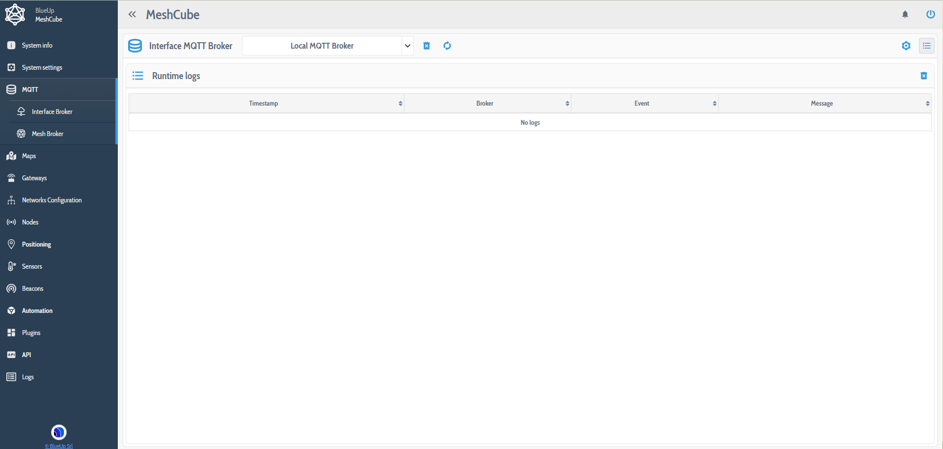
Broker log
This section contains the Logs provided by the MQTT Broker. To enter the Broker log section press on  icon in the upper right corner.
Mesh broker
Mesh MQTT Broker Packets
This section contains the Packets received from Mesh devices.
The packets section can be opened by pressing  button.
Useful right side buttons are:
- Toggle packet listener
 to enable / disable the packet reception;
 - Toggle autoscroll
 to enable page autoscroll to display the new packets;
 - Delete displayed logs to delete the displayed packets.

MQTT Broker Log
This section contains the Logs provided by the MQTT Broker.
The log section can be reached by pressing button.

Maps
The Maps section allows to visualize the position of the tags on the map. To do that the Sink and the Router nodes (positioning anchors) should be placed on the map so that the tags position can be computed.
In the following are described the steps to configure the map.

- In the Maps tab in the upper right corner press on Create new map . To create the map the user has to upload the map image and define the Scale of the map in pixels per meter. This parameter is important to calculate the position of the tag, converting the pixels in the actual distance from the anchor to the tag.
When creating a map it is possible to select the option Convert position to geographic coordinates. With this option, by specifying the geographic coordinates of a point on the map, it is possible to retrieve both the XY position on the map and geographic position of an object on the map.
- For an easier anchor placement on the map it is possible to place the guides. To do that, enable the Guides in Layers menu and then in Actions menu select Add Vertical / Horizontal Guide. To move the guide, press with the left mouse button on the edge of the guide and move it. To eliminate the guide from the map, click with the right button on one of its ends.

- Create the Zones on the map. This is useful in case the user wants to compute the position of the tag based on the zones. In Actions menu press on Create new zone. Using the left mouse button, press in a spot where one vertex of the zone will be and drag from that point to build a polygon. Release the mouse button. If the zone is not squared, but is an irregular polygon, other vertexes can be added. To add a new vertex, press Shift and press with the mouse on one of the vertexes. The new vertex will be added on the right with respect to the vertex on which you have pressed.
To move a vertex, press and drag it in the desired position (press Ctrl to stick the vertex to the guide).
When the zone is setup, press Enter to save the created zone.
- Create a new exclusion zone. This feature has been added in the latest releases and it allows to define the zones where the Tag can not physically enter. For example, in a warehouse an operator that has a tag on him for sure can not climb on the shelves. But sometimes, because of some signal strengths, the tag calculated position may be located on a shelf. To avoid this an exclusion zone can be defined.
Press enter after drawing the desired exclusion zone to save it.
- Select Place Sink/Routers on the map in Actions menu, select the Sink or Router to place on the map and place it on the map. To move a Sink or Router:
- right click on it and a menu will appear, from which it is possible to move or delete a node;
- or press Shift and drag the router. Release and press YES if the position if right.

- Also, it is possible to design the placement of the routers, without physically placing them on the map. This is possible using the Placeholders. In actions menu, select Add placeholder, define the number and the color and place it on the map.
Once that the project is ready, to place the routers in the place of the placeholders, right click on the placeholder, press on Place item here and select the node to place.
In Layers menu it is possible to select the items visible on the map, such as the Guides, Zones, Mesh Nodes, Tags, and others.

Two important items are Tag Accuracy and Positioning anchors.
Tag Accuracy, applied to the tags, shows the accuracy range of the position of the Tag.
Positioning anchors for each tag shows which anchors contribute to the position calculation and the RSSI value between tag and anchors.
On the bottom of the page there are some features that can be useful:
- Tag filter where the user can enter the tag ID or Alias (if set) to show on the map only that tag;
- Reset zoom
 to restore the view of the map to the original zoom;
 - No tool selected
 ;
; - Map move
 to move the view of the map;
 - Map area selection
 to zoom the map in a selected area;
 - Measure distance
 to measure the distance between two points on the map.
Gateways
This tab contains the list and information of all the Gateways Connected to the service.
There are 3 ways to connect the gateways to the MeshCube:
- In Gateway section, press on . The system will scan all the gateways that are available in the network. After, press on
 button near the gateway you want to connect.
When connecting the gateway, will appear a pop-up asking the password of the gateway. If you are connecting a TinyGateway the password field can be left empty.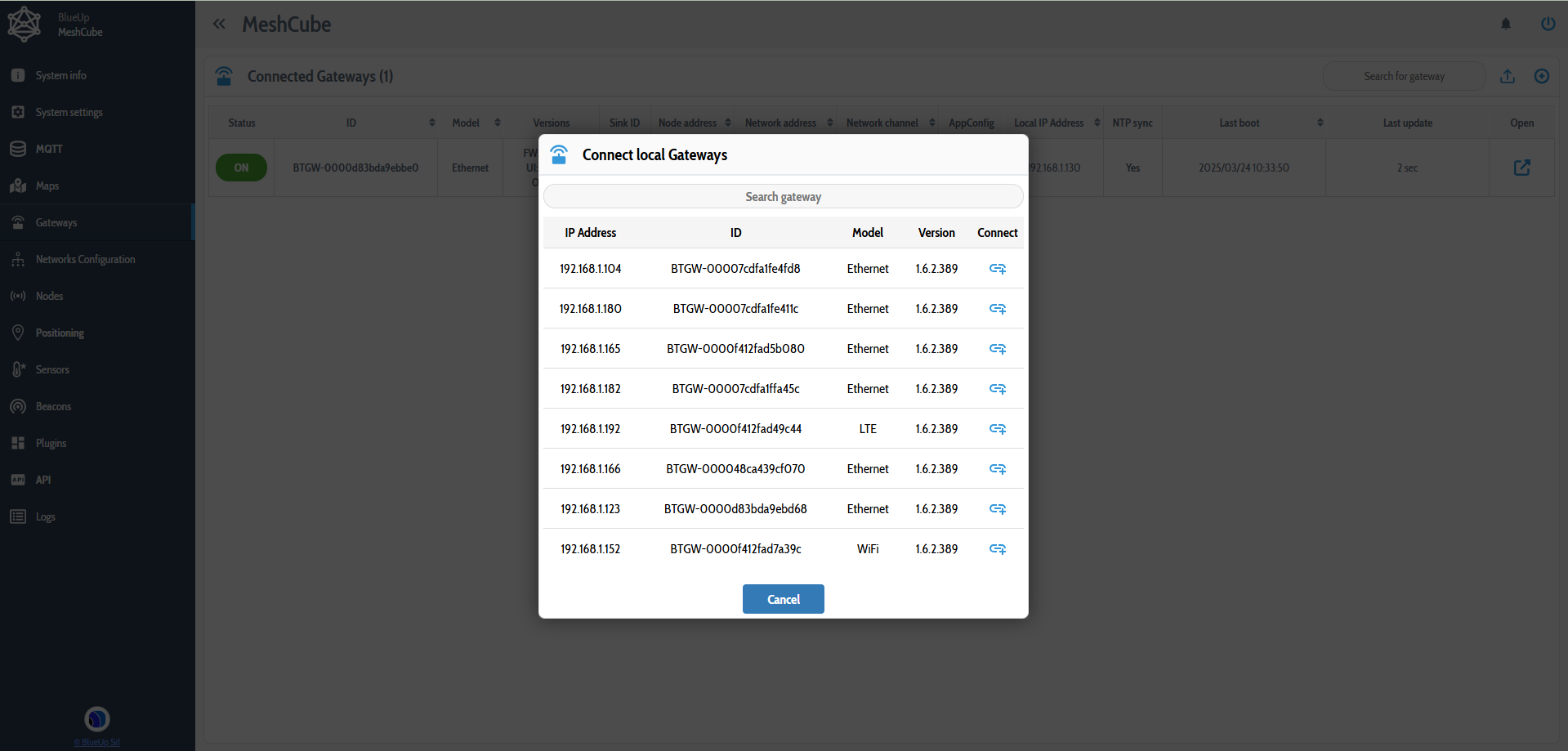
- Periodically the system scans the network and reports the new gateways found in the local network in a notification. To connect a gateway, open the notification manager , search the desired gateway and press Click to register to connect it to your MeshCube.

- In case the gateway and MeshCube are not in the same network, please follow the connection steps described here.
The Status column shows the status of the Gateway, that can be Online or Offline. In case the gateway is offline the row corresponding to the offline gateway will have a light-red background.
The gateway row can assume also a light-orange background meaning that the Sink functionality of the gateway (Sink stack) is offline.

For all the TinyGateway gateways there is a direct link to the Web Interface of the Gateway  . This allows to open, inside the MeshCube interface, the web interface of the chosen TinyGateway, that allows to configure the gateway and all its functionalities.
Refer to the manuals of TinyGateway Wirepas for more information about the TinyGateway web interface and configuration.
Networks configuration
MeshCube interface can handle multiple Networks at the same time. Make sure to choose the right network when configuring the devices.
The network configuration tab allows to set a custom configuration to the Mesh Nodes.
The configuration can be applied to one Network at a time. For this reason, if multiple networks are handled by the system, make sure to choose the right network when sending the configuration.

For all the networks, at the first start, a default configuration is already present in the MeshCube web interface.
In this section the user can:
- create new configuration from scratch in the upper right corner of the page. Here the user can start setting up a new configuration or can import the AppConfig and the configuration will be generated accordingly;
- apply a configuration to the network
 ;
; - modify a configuration template
 ;
; - clone a configuration and then modify it
 ;
; - download the AppConfig of a configuration
 ;
; - export the configuration template as JSON

- delete a configuration template
 (the default configuration, that is always present at the first start, can not be deleted).
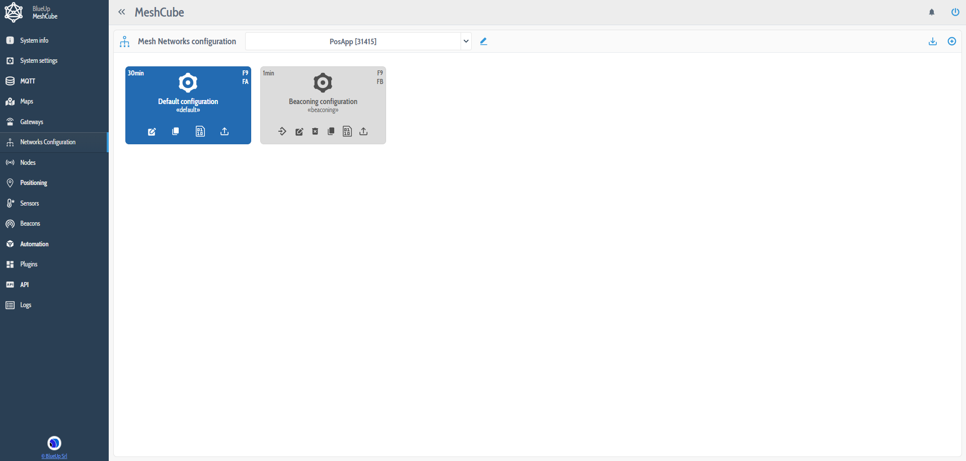
The possible configuration packets are:
- Diagnostics interval (always present), that is how often the devices should send diagnostics information;
- Anchor configuration (Router nodes) - F9 is the default anchor class;
- Tag configuration (Non Router nodes):
- FA - Default Asset Tag configuration;
- FB - Default Personal Tag configuration;
- Additional custom node classes, from FC up to FF.
- Change node class - available from MeshCube v.6.1
- Change Network parameters - available from MeshCube v.6.1
Note: Node class configurations are optional. The user can define or not the configuration for a given node class.

A problem that could arise when defining the configuration for multiple node classes is the length of the configuration. From the interface, the configuration is translated into an AppConfig, that is a stream of bytes. This stream must have a maximum length of 80 bytes. If the network configuration, after it has been translated into bytes, exceeds the 80 bytes an error will appear.
Note: to make the byte stream shorter, eliminate useless configuration parameters (accelerometer, beaconing) or configure one (maximum 2) node class(es) at a time.

From MeshCube v.6.3.2503.2100 it is also possible to clone a configuration for router and non router node from one class to another. On the corresponding tab the clone can be done by pressing  icon. This operation clones the configuration set for one node class to another node class (from Router to Router or Non router to non router).
Router node configuration
This setting allows to configure all the Router Nodes of the Network at the same time. The settings include:
- sensing interval - update interval of sensor measurements;
- alerts enable - if mounted, enables LED and/or button functioning;
- Off by position setting allows to disable the anchors when they are in horizontal position. This setting is used mainly during transportation of the devices to avoid battery discharges;
- configuration of the Beaconing. The supported beaconing packet types for the Router Nodes are:
- iBeacon
- Eddystone-UID.

Non Router node configuration
As for the Non Router Nodes, we can distinguish between Default Asset (FA), Default Personal Tags (FB) and other configurable node classes (up to FF). The distinction is made to allow the user to configure the two types of the Tags with different parameters, if needed.
The Non Router Node Configuration is divided into 3 subsections, that group configuration parameters:
- Base configuration allows to configure base tag functionality parameters:
- Positioning interval for all states;
- Positioning Timeout for default, motion and alarm states;
- Autoscan enable to define in which states the tag should remain in autoscan. Note: when positioning interval is less than 30 sec, the tag automatically enters Autoscan mode;
- Button / Alerts enable, if mounted;
- Accelerometer enabled. If enabled, also Motion threshold, motion duration and advanced accelerometer configuration can be modified;
- Motion threshold defines the intensity of movement. Acceleration needs to be greater than the threshold to detect movement. Motion threshold is defined in mG and 160mG is a sufficient value for both asset and people tracking to not to have false movement detection even if the tag is worn pendent around the neck and there are small oscillations of the tag;
- Motion duration defines the minimum time period for which the acceleration must be greater than the threshold to detect movement;
- Advanced Accelerometer Configuration allows to configure advanced accelerometer functionalities, other then motion detection. Each accelerometer functionality has its own configurable parameters. For more information on the accelerometer modes refer to Mobile Tag Configuration Packet format. Other Accelerometer modes are:
- Position
- Freefall
- Shock
- Mandown
- Beaconing Configuration allows to configure beaconing on the Mesh tags. The supported beaconing packet types are:
- Quuppa
- iBeacon
- Safety.

Change node class
This configuration is used when it is necessary to change the class type to the device.
Note: you can not change the type from tag to anchor and viceversa, only from tag to tag or anchor to anchor.
When adding the Change node class configuration packet, you will be asked the target node class to change from.
The configuration packet is composed by:
- Destination node class - which is the new node class to change to;
- Start node address - used to specify the range of node addresses to change the class. If left empty the node class change will start from the first available node address;
- End node address - used to specify the range of node addresses to change the class. If left empty the node class change will end with the last available node address.

Change network parameters
WARNING
The network parameters change is an advanced settings and should be applied only when strictly necessary.If some parameters are set wrong, the change network parameters operation is irreversible and the devices may be unrecoverable.
Before changing the network parameters, make sure that the tags you are changing the network to are near the Sink. Also, we suggest to have 2 Sinks already connected to the system: one configured with the source network and one with the destination network, to be able to control the devices changing the network.
When adding the Change network parameters configuration packet, you will be asked the target node class to change from. If more than one node classes have to change the network parameters, you will have to repeat the configuration for each class.
The fields that compose the configuration are:
- Start node address - used to specify the range of node addresses to change the network parameters. If left empty the node class change will start from the first available node address;
- End node address - used to specify the range of node addresses to change the network parameters. If left empty the node class change will end with the last available node address;
- Destination network address - is the New Network address you want to apply to the devices;
- Destination network channel - is the new network channel to apply to the devices;
- Encryption/authentication keys to set if you require them, otherwise leave empty.

Nodes
This section contains the list of all the detected mesh Nodes, divided into Sink, Router and Non Router Nodes. For each Node type the table contains information about the nodes.
In case multiple networks are defined in the system, the user can choose whether to display all the nodes or only the nodes belonging to a specific network.
Additionally, in the latest updates has been added the possibility to define the group to which a node belongs.
To add a node to a group, press on Not set field under the Group column. A pop-up menu will appear from which it is possible to select a group or to create a new group to add the node to.
Unless the node group is removed, the node group is stored in the nodes database. This means that if the node is removed from the system, after it is reconnected to the system the group and the alias of the node are retrieved from the database.

To filter the displayed nodes press on  button in the upper right corner and:
- select the group nodes to display; or
- show all to display all the nodes of the system; or
- show not assigned to display only the nodes that do not belong to any group.

For the Sink nodes, the first column shows whether the Wirepas Stack is running or not. If the stack state if offline the gateway sink functionality is not running, the stack state icon becomes Red and the row of the corresponding Sink will have a light-orange background.
If the gateway (that is configured as Sink) is offline, the background of the row becomes light-red.
For the router and non router nodes, the ID field can assume different colors, based on the state of the device:
- Green - the device is online and correctly working;
- Grey - the device has been loaded from the cache of the system. That is, after the reboot of the system, the device has not been detected by the system, even if the device has remained in the memory of the system;
- Red - the device is not detected or offline.
When the device is red it is possible to remove the not detected devices from the Nodes table by pressing the icon in the row corresponding to the not detected node.
If there are many red nodes, it is possible to remove all the not detected nodes of the same type (routers or non routers) by pressing the icon on the right on the same line of the node type.
For both Router and Non router nodes it is possible to set the Detection timeout by pressing  button. The Detection Timeout is the time interval after which the tag is considered inactive when there is no update from the tag. After the timeout period the tag can be deleted from the system.
By default the detection timeout is set to 24h. The user can leave it as it is or adjust to the need and to the use case.

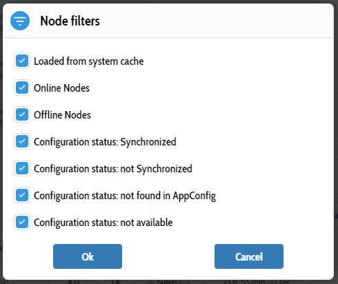
Also, the router and non router nodes that are displayed can be filtered. By pressing the  button for the Router or Non Router nodes, a menu appears from which the user can choose the criteria following which the nodes are displayed in this tab.
When all parameters are chosen, all the nodes of the system will be displayed.
The columns of the Router Nodes contain:
- information about the node: ID, Network ID, Alias, if set;
- Wirepas data: Radio Installation quality, Operation mode (refer to Operation Modes);
- Config allows to display the current node configuration. The Config button can have four states, with different colors:
- Grey - the system has not received the node configuration yet;
- Red - the configuration received from the node is different from the Network Configuration set in the interface. It can happen, for example, when the new configuration has been set and the nodes have not been configured yet;
- Yellow - the node class configuration in not present in the last Network Configuration. This can happen since we can add or eliminate node classes when configuring the nodes in the network;
- Green - the configuration of the device is the same as the one set in the network;
- Send command button allows to send one of the possible commands to the device. The commands feature is described in the Commands section.
As for the Non-Router nodes the columns are:
- information about the node: ID, Network ID, Alias, if set;
- State data:
- State/Mode (refer to tag states);
- State time shows for how long the node has been in that state;
- Last positioning is the time elapsed from the reception of the latest positioning packet from the node;
- Last config update is the time elapsed from the reception of the latest configuration packet from the node;
- Last update is the time elapsed from the last update of the mesh network;
- Config allows to display the current node configuration. The Config button can have four states, with different colors:
- Grey - the system has not received the node configuration yet;
- Red - the configuration received from the node is different from the Network Configuration set in the interface. It can happen, for example, when the new configuration has been set and the nodes have not been configured yet;
- Yellow - the node class configuration in not present in the last Network Configuration. This can happen since we can add or eliminate node classes when configuring the nodes in the network;
- Green - the configuration of the device is the same as the one set in the network;
- Send command button that allows to send one of the possible commands to the device. The commands feature is described in the Commands section.
Note: For Router and Non-router nodes the columns displayed in the table are configurable. The user can select the nodes to display in the Filter Columns menu on the right.

Commands
It is possible to send commands to both Router and Non Router nodes.
The commands that can be sent to the nodes are:
- Reboot the device;
- Change node class (from MeshCube v.6.1);
- Button Enable / Disable;
- Alert Enable / Disable - the user can manually compose the alert or use an alert template created in Alert template setting;
- GPIO Configuration to configure the IO Pins (if available on the device);
- Query current configuration;
- Query current position.
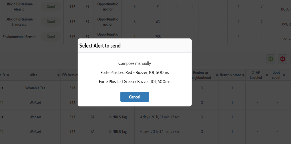
The alert can be sent:
- Unicast, to one node at a time;
- Multicast, to one node class at a time. If the user wants to send a command to all Router or Non router nodes, and if there are more than one node class, the user will be asked to choose the node class to send the command to.

Starting from the MeshCube version 6.0.1.x it is possible to request an ACK when sending a command.
This request allows to track the command reception at the node side. If the command received by the node within the set time interval, the node sends back an ACK, that is also visualized in the MeshCube interface.
Instead, if the node is not reachable by the network within the set time interval, no ACK is received and also a notification is sent on the MeshCube interface.

Network tree
When pressing  button in the upper right corner, the tree representation of the current network will appear.
This representation allows to inspect the network structure and to see how it is organized, i.e., how the single nodes connect to the sink, with the related link quality.

Firmware upgrade
In the right upper corner there is the Firmware Upgrade menu ![]() .
.
To upgrade the firmware of the devices, first select the network to upgrade the firmware to.

After that, upload the OTA firmware file sent by BlueUp for devices firmware upgrade.

The firmware upgrade will be performed as a background process and the user can follow the process through the notifications from the system.

Positioning
When the Router Nodes are placed on the Map and are configured to detect the devices in the nearhood, these Nodes become Anchors.
While when the Non Router Nodes are configured to be localized, they become Tags.
When the Nodes are configured as Anchors and Tags they contribute to the positioning functionality of the system.
Mesh Anchors
In this tab are listed all the Router Nodes configured as Mesh Anchors. For each Anchor the available information is listed in the table, having the following fields:
- Basic information about the anchor, such as ID, Network ID, Alias (if set);
- Information about the position of the anchor, including the Map, Zone (if defined on the map), Position coordinates;
-
Information about positioning settings of the anchor:
- Positioning enabled;
- Calibrated RSSI is the RSSI value at the distance of 1 meter from the anchor;
- RSSI Offset is the RSSI adjustment with respect to the calibrated value;
- N is the environmental factor used to evaluate the distance between the anchor and the tag;
- Battery state of the anchor.

The positioning settings can be modified at any moment, for each anchor separately or for all anchors at the same time, by pressing the ![]() icon.
icon.

Mesh Tags
In this section are listed all the detected Non Router Nodes configured as Mesh Tags.
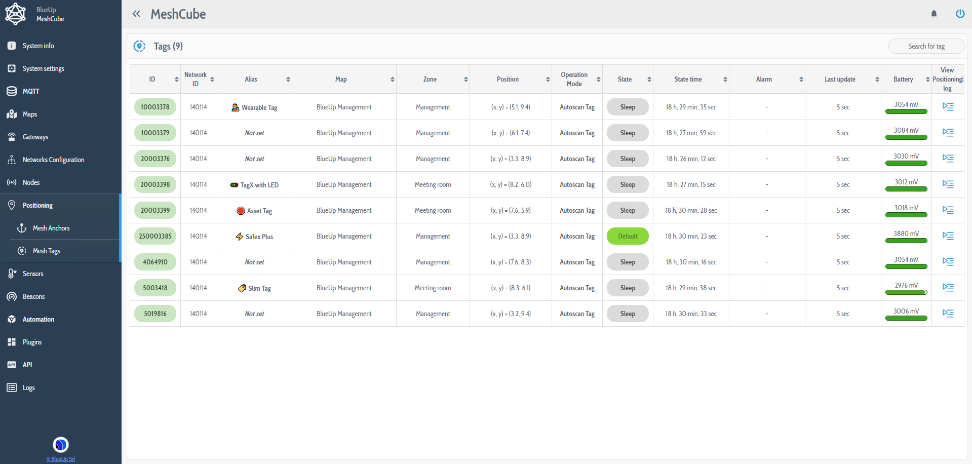
For each Tag the available information is listed in the table, having the following fields:
- Basic information about the tag, such as ID, Network ID, Alias (if set);
- Information about the position of the tag, including the Map, Zone (if defined on the map), Position coordinates;
- Information about the current operational state of the tag:
- Operation mode can be NRLS Tag or Autoscan Tag (for more information refer to Operation Modes);
- State of the tag, that can be Default, Motion, Alarm or Sleep (for more information refer to Wirepas-enabled positioning application);
- State Time indicates for how long the tag has been in the current state;
- Alarm indicates what condition had triggered the alarm state. The possible alarm triggers are: button pressed, Mandown (if configured), Shock (if configured);
- Battery state of the tag;
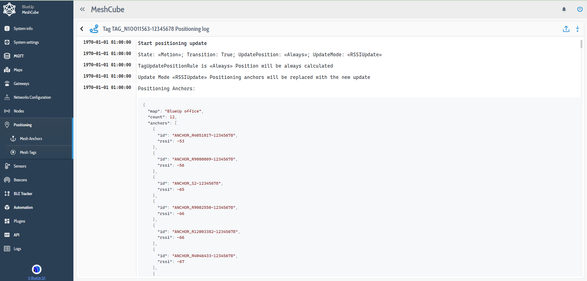
- Position log. When pressed, a new window will open where will be displayed the logs related to the tag. In these logs are shown the steps that are performed to evaluate the position of the tag. This functionality is useful when the user wants to go into detail on how the position is calculated.
Sensors
Sensors section collects all the nodes that are designed and configured as Sensors. For each sensor are displayed data of the available sensors, that can be:
- Temperature in Celsius or Fahrenheit, as set in Mesh Sensors settings;
- CO2 in parts-per-million;
- Humidity in percent;
- Pressure in Pascal.

For each sensor it is possible to:
- Refresh the measurement
 ;
; - Set or change the alias of the sensor ;
- View the charts
 . This allows to display and monitor the behavior of one measured quantity at a time of the last 24 hours.

Beacons
Beacons are Nodes with Beaconing enabled when configuring the Nodes, that is configurable for both Anchors and Tags, as described in networks configuration section.
The possible Beaconing types are
-
for Anchors:
- iBeacon
- Eddystone-UID
-
for Tags:
- iBeacon
- Safety
- Quuppa Emulation Mode.
The fields that are displayed for each beacon are:
- Beaconing type;
- Beaconing frame information;
- Advertising interval;
- Advertising TX power.
![]()
Plugins
Plugins are additional functionalities to the software that are different from the embedded ones. With the plugins the user can extend the native functionalities, without changing the basic structure of MeshCube.
MeshCube has pre-installed one plugin: Sample Email notification to allow the users to evaluate and explore the plugins strength.
Other Plugins are already available to be integrated in your MeshCube. Otherwise it is possible to discuss the possibility of developing a plugin for your own use case and for your own necessity.
In any case, to have more information you can reach us by opening a ticket or by writing an email at support@blueupbeacons.com

Sample Email notification
This plugin enables the email notifications for:
- System start/stop
- License status
- Gateways status changes
- Low battery nodes
When the plugin is configured and when one of the above mentioned events occurs, the system sends an email to the configured email address(es) to notify which event has occurred.
Configuration
The user should have an SMTP Server that can be used for email sending and the system must have the Email Service properly configured.
First, the Email service should be configured:
- Define an SMTP Server in Settings » IO » SMTP Servers
- Configure the service in Settings » System » Email Service specifying:
- The SMTP Server created at point 1
- The sender description (optional)
- The sender email address, that is the email address the MeshCube will use to send the emails
To start receiving the email notifications, in the setting of the plugin the user should setup the following parameters:
- Enter a valid list of email addresses the email notifications will be sent to
- Select the events that trigger the email sending
- Save the configuration
Once that one of the selected events occurs, MeshCube will send an email to the configured email addresses.

API
The MeshCube platform also has a little documentation section, where are documented:
- Events generated by the system;
- HTTP APIs;
- FTR Queries.

FTR Queries
FTR Queries are scripts that allow to define some functions for the call of some APIs.
FTR stands for Filter, Transform, Reduce and these functions are to be written in JavaScript.
When adding a new query (by pressing ) the user has to define:
- the API path, that is the API call to which the FTR will be applied. The currently supported API calls are:
/api/gateways/api/maps/api/nodes/api/tags
- the name of the query without blank spaces;
- query description;

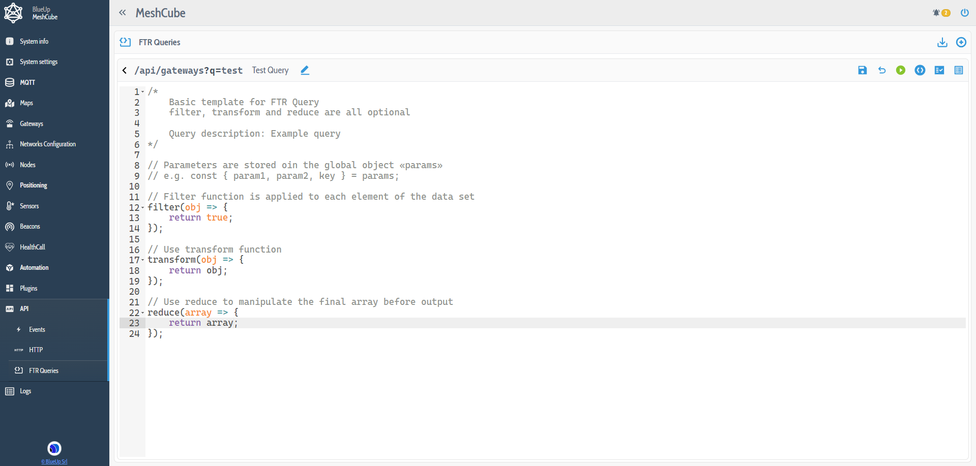
The script can contain Filter, Transform and Reduce functions, described in the following.
All the three functions are optional
When creating a new query, a query template will open.
Above the code field, there are some useful buttons:
- to save the code changes;
- to edit the Api, name and description of the query;
- to export the query;
- to delete the query;
- to enable / disable the query. When the query is disabled, calling the API with query will return the same response as calling the API without query;
 to automatically format the code;
 to heck the validity of the code;
 to show / hide the list of defined parameters. When showing, it is possible also to define a new parameter.
Filter
When defining the Filter function, it is applied to each element of the data set. When defining the filtering rule, the data set will be reduced to the only elements that satisfy the filtering condition.
Consider, for example, the /api/nodes call that returns the array of all the nodes in the system. The user may want to retrieve only the information regarding the Router nodes. This is possible by defining the filter function.
Example in which are returned only the non router nodes:
Transform
The Transform function is used to retrieve only the desired fields of the data set.
Taking as example the /api/tags call, it is possible to take only the fields the user is interested in.
Example in which are retrieved only id, alias and battery of the tags:
Reduce
The reduce function is used to manipulate the output array.
A possible usage is to return only the number of elements that satisfy the query:
After setting up the FTR Query, save it and enable the query, by pressing button.
To call the defined API with the defined query, the API call structure is (example for /api/nodes):
<meshcube_ip_address>/api/nodes?q=<query-name>
Logs
System logs
The Logs keep track of the system messages that can be used to track the software activities. The logs can be accessed by pressing  button in the upper right corner.
It is possible to filter the logs that are displayed by enabling or disabling different log levels, in the upper left side of the page, by choosing among:
- Information
- Warnings
- Errors
- Debug
- Verbose

System events
The system Events page can be accessed by pressing  button in the upper right corner.
These logs contain all the events of the system, if the event tracking is enabled by pressing the the  button.
The full description of the events can be checked in API Events tab.
